6pm Wednesday I was in Van Leer wanting to return home and it was raining outside. Last post I had made my attempts to partially waterproof the scooter and was looking forward to a way to test them out. Rather than carefully submerging the body into a controlled volume of water, Aaron and I said screw it and jumped into the massive flooding that is Atlanta.
The verdict is that the scooter is water resistant but in the wrong way. The top is somehow water permeable yet the bottom retains it very well. Something to be said about the sealing job I did.
I actually had to pour my scooter over a sink to rid of the water. I suppose the takeaway from this is that if I want water resistance, I cannot have accessibility to the internals.
That night I lost ANOTHER HK cartroller and an arduino nano. This project is eating up electronics lately.
Now today, I was beasting it to my Heat Transfer class, traveling no less than 15 mph, when I curb jumped and splattered on the concrete.
Turns out that jump was the last straw on the threads holding the steering column to the base chassis and all of them fell to sheer. I expect the quickest fixes will be the rebuild the plate from steel (instead of Aluminum) or to use a countersink screw and locknut combination (both of which I have).
I'm going to sleep.
Friday, February 3, 2012
Monday, January 30, 2012
Razor Wind: I Hate Rain Edition (Upgrades!)
It is a well known fact that Saftey Razor may have been better than Razor Wind for one particular reason. Safety Razor's electronics were bundled and epoxy potted on the end of the motor, making for a very weatherproof and indestructible setup. While Razor Wind had better performance characteristics, it did not have nearly the same luck.
Last week Monday, we had some rather harsh thunderstorms roll over campus and I decided to ride the scooter in the wet. Story short, I noticed a little puff of smoke that was formerly the servo tester. I almost wished it was the esc, because unlike the servo tester, I have multiples of the HK escs.
Downtime means upgrade time, so let us look down the list of things I've wanted to do but never felt like opening a working device to implement.
Speaking of indicators, Turnigy engineers impress me with the concept of a 'solder fuse', which tripped internally in my 6s 5000mAh lipoly pack when the esc blew. Probably saved me another 70 dollars right there.
This result was frustrating but not deterring. Using my last remaining spare, I decided to go forward with a variation of the mod. This time, we should use the heat transfer traces. This was nice because I only had the invert the capacitors.
Instead of solder paste, I pulled one of the heat transfer pads off the undersides of the heatsinks and tossed it between the aluminum heat spreader and the traces. This version is working flawlessly.
OKAY, so mod #1 completed. Now we can hit up weatherproofing efforts.
I figured most of the moisture was entering though the ventilation zone on the rear end but it couldnt hurt to seal up all the cracks. While performing the esc mod, I grabbed some RTV Silicon gasket maker and filled in the corners like caulking.
The opening over the esc was covered using a panel of 1/32" 7075 Al. I took the opportunity to make a water right exit for the esc plugs, which not only looks cool but also stabilizes the connection.
Note the blue edge around the top cover. The RTV Silicon seeped from the edges there a bit.
Fangoriously bright LEDs to indicate power through the scooter.
I hope I never have to test the functionality of my sealing job... Item #2 complete.
From my experiences letting other people try riding my scooter, it was clear that control was not its strong point. I attribute this to the rather shoddy rapid prototyped throttle I made last semester and the servo tester used to convert A to D.
So the throttle crazy began. I purchased maybe three different types of throttles (with spares. Say, does anyone need a throttle?) to select one thumb throttle from an ebay vendor selling 'American Chariots'.
Should you decide to purchase one, I'll save you the setup finagling and tell you the RED wire is +5V, the GREEN wire is output, and the YELLOW wire is ground. Not intuitive at all and I suppose I should be fortunate I didnt destory the thing.
I paired this new throttle up with an Arduino Nano (knockoff) to replace the servo tester. Not only was this guy smaller, but with some slick coding from Shane Colton I was granted control variables to handle throttle limiting and ramping rates. Exciting!
You can follow that right? Shane's Code can be found at the bottom of this Instructables page.
Items 3 and 4 completed! Finally, nothing makes things look awesomer than a bunch of reflective stickers.
Arduino Pride!
Last week Monday, we had some rather harsh thunderstorms roll over campus and I decided to ride the scooter in the wet. Story short, I noticed a little puff of smoke that was formerly the servo tester. I almost wished it was the esc, because unlike the servo tester, I have multiples of the HK escs.
Downtime means upgrade time, so let us look down the list of things I've wanted to do but never felt like opening a working device to implement.
- Weatherproofing
- New Throttle
- Controlled Response from Throttle
- Fanless esc (no random protrusion from the top)
- Make it look pretty
Over the week, I've had the chance to tackle ALL OF THEM.
First, the esc needed a low profile modification in order to seal the upper deck. Simply removing the fan would have done the trick but without convective cooling I was worried about esc overtemp. So I went one step further and increased the size of my heatsink... THE ENTIRE CHASSIS.
Here we see the heatsink off the boards cooling WTF?! Traces?!
Even though the SO-8 package MOSFETs are designed to cool through the PCB, I wasn't convinced it was the best way to dissipate heat. The other side of the board had the ass-ton of FETs required to run, *shudder*, 150A.
So the obvious solution in my mind (at the time) was to resolder the components such that the FETs were exposed. So here we go desoldering all the headers and caps.
First, the esc needed a low profile modification in order to seal the upper deck. Simply removing the fan would have done the trick but without convective cooling I was worried about esc overtemp. So I went one step further and increased the size of my heatsink... THE ENTIRE CHASSIS.
Here we see the heatsink off the boards cooling WTF?! Traces?!
Even though the SO-8 package MOSFETs are designed to cool through the PCB, I wasn't convinced it was the best way to dissipate heat. The other side of the board had the ass-ton of FETs required to run, *shudder*, 150A.
So the obvious solution in my mind (at the time) was to resolder the components such that the FETs were exposed. So here we go desoldering all the headers and caps.
After an hour of desoldering, time to resolder.
The Aluminum of course would then be mounted against the base plate and the entire thing would be clamped down with some extra 2-56 cap screws. It is awesomely tiny compared to the stock product!
It looked pretty shnazzy after completion. Some thermal compound would be added between the FETs and the aluminum heat spreader shown below.
The Aluminum of course would then be mounted against the base plate and the entire thing would be clamped down with some extra 2-56 cap screws. It is awesomely tiny compared to the stock product!
Testing indicated that everything worked as planned, but horror struck with I added the SILICON thermal paste to the FETs. I powered it up and I instantly lost three FETs on the startup tones.
The faults indicate that there was a short, which perplexes me because I had it running the night before. The only thing different between the two setups was the addition of NON-CONDUCTIVE thermal paste. Needless to say I'll be doing this differently next time. (un)Fortunately, Digikey has the NTMFS4833N power MOSFET for min purchase of 5000. Anybody else want to split a pack?Speaking of indicators, Turnigy engineers impress me with the concept of a 'solder fuse', which tripped internally in my 6s 5000mAh lipoly pack when the esc blew. Probably saved me another 70 dollars right there.
This result was frustrating but not deterring. Using my last remaining spare, I decided to go forward with a variation of the mod. This time, we should use the heat transfer traces. This was nice because I only had the invert the capacitors.
Instead of solder paste, I pulled one of the heat transfer pads off the undersides of the heatsinks and tossed it between the aluminum heat spreader and the traces. This version is working flawlessly.
OKAY, so mod #1 completed. Now we can hit up weatherproofing efforts.
I figured most of the moisture was entering though the ventilation zone on the rear end but it couldnt hurt to seal up all the cracks. While performing the esc mod, I grabbed some RTV Silicon gasket maker and filled in the corners like caulking.
The opening over the esc was covered using a panel of 1/32" 7075 Al. I took the opportunity to make a water right exit for the esc plugs, which not only looks cool but also stabilizes the connection.
Note the blue edge around the top cover. The RTV Silicon seeped from the edges there a bit.
Fangoriously bright LEDs to indicate power through the scooter.
I hope I never have to test the functionality of my sealing job... Item #2 complete.
From my experiences letting other people try riding my scooter, it was clear that control was not its strong point. I attribute this to the rather shoddy rapid prototyped throttle I made last semester and the servo tester used to convert A to D.
So the throttle crazy began. I purchased maybe three different types of throttles (with spares. Say, does anyone need a throttle?) to select one thumb throttle from an ebay vendor selling 'American Chariots'.
Should you decide to purchase one, I'll save you the setup finagling and tell you the RED wire is +5V, the GREEN wire is output, and the YELLOW wire is ground. Not intuitive at all and I suppose I should be fortunate I didnt destory the thing.
I paired this new throttle up with an Arduino Nano (knockoff) to replace the servo tester. Not only was this guy smaller, but with some slick coding from Shane Colton I was granted control variables to handle throttle limiting and ramping rates. Exciting!
You can follow that right? Shane's Code can be found at the bottom of this Instructables page.
Items 3 and 4 completed! Finally, nothing makes things look awesomer than a bunch of reflective stickers.
Arduino Pride!
Sunday, January 29, 2012
Alternative Solutions for Things That Don't Fit
For people who find incompatibilities between some new object and the space the old one sat, there are really three options:
- Get a new environment
- Don't use the new object
- Rebuild ALL THE THINGS
I have a SFF case for my Lenovo M90 Desktop and wanted to increase my gaming/rendering performance by purchasing an new GPU. I settled on this nice Asus board, which had a ATI HD mobility Radeon 6570 attached to it, but when it came I quickly realized that it didn't fit in my case.
The top board is the new one and the bottom board is a NVIDIA GeForce 310. There was at least some .25" to .375" height difference due to the heatsink and as a result it touched the hard disk mounting bracket.
Yeah that's not much space...
Everyone seemed to suggest to buy a new case (choice #1). Myself, being a maker and machinist at heart, decided on choice #3.
Tada! It was easier to move the hard drive than move the PCI-E slot, so I redesigned the mounting case and shifted its location a fractional amount away from the graphics unit. Because we have 3D printers in the studio, I decided it was time to massively abuse them.
6 hours later...
Made off the Invention Studio's uPrint.
Old and the New
Part of the adaptation included slicing the wings off this cast aluminum piece. At this point, im pretty sure the warranty is void.
The new mount uses 6-32 screws to attach to the hard drive, and some small perforations to clip onto the inside of the case.
To keep things from bouncing around, I threw in stacks of leftover rubber grommets I bought for the Hardboard Project. Glad I could find a use for them.
So there it sits complete! Now I know what many of you are thinking. You are using melted plastic to hold a part nearby a notoriously hot object. Won't it melt? The answer is hopefully not. ABS melts at somewhere around 225 deg F, which converts to 107.2 deg C. The heatsink is not actually touching the ABS, and the convection currents internal to the PC should work in my favor, decreasing the edge temperature of the heatsink alloy and cooling the ABS. Besides, should my GPU get over 100 deg C I think I have larger problems to worry about.
And oh hey! 3D printed Soap!
So there it sits complete! Now I know what many of you are thinking. You are using melted plastic to hold a part nearby a notoriously hot object. Won't it melt? The answer is hopefully not. ABS melts at somewhere around 225 deg F, which converts to 107.2 deg C. The heatsink is not actually touching the ABS, and the convection currents internal to the PC should work in my favor, decreasing the edge temperature of the heatsink alloy and cooling the ABS. Besides, should my GPU get over 100 deg C I think I have larger problems to worry about.
And oh hey! 3D printed Soap!
Monday, January 23, 2012
Wheelpod: Chain Conversion
I found out about two weeks after I placed my order that McMaster's custom chain length item is meant for link numbers divisible by two. Awww shucks, I couldnt trick the system. I calculated previously a length of 51 links for a perfect chain length so they called me up one morning and handed me the unfortunate news. I would have been bummed, except I had already gotten tired of waiting and decided to beat it anyway with some surplus chain given to me by Aaron Fan.
The sprocket was the tricky part. Because I'm cheap, I neglected to buy any appropriately thick metal to cut #25 sprockets out on the waterjet. So I ended up with a 3/16" thick plate of mystery steel from the scrap pile. Most sprockets of #25 are some 3/32" thick with an edge taper. This piece of metal would require a good amount of working with some care for symmetry. My first thoughts were to add the bevels on the lathe, but we didnt have tooling shallow enough not did I want to disrupt the squareness of the toolpost. This is what I ended up doing.
Now excuse me as I tempt fate with my 30mph nonsense on wheels.
The sprocket was the tricky part. Because I'm cheap, I neglected to buy any appropriately thick metal to cut #25 sprockets out on the waterjet. So I ended up with a 3/16" thick plate of mystery steel from the scrap pile. Most sprockets of #25 are some 3/32" thick with an edge taper. This piece of metal would require a good amount of working with some care for symmetry. My first thoughts were to add the bevels on the lathe, but we didnt have tooling shallow enough not did I want to disrupt the squareness of the toolpost. This is what I ended up doing.
Ah yes, I feel like a high school student again. That is a right-angle drill chucking a cap screw, which is holding a plate of aluminum that has the sprocket bolted to it. The assembly spins against a belt sander and adds a bevel (slowly).
Another shot.
Surprisingly enough, the technique worked well.
Thursday, December 29, 2011
I Accidentally...
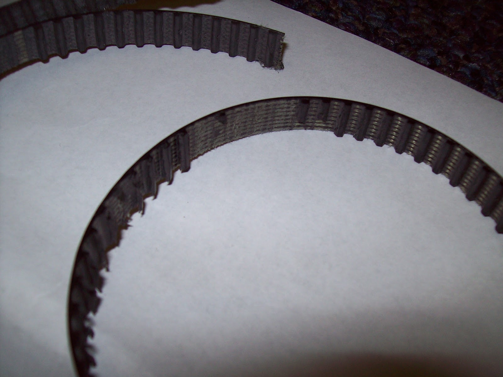
...my last urethane belt. Look at that snaggletooth.
As I began reassembling Razor Wind after cleaning it up, I neglected to check the motor direction before stepping outside for a test run. After the initial kick start, I threw the throttle only for it to instantaneously brake and change directions. Stripped all the teeth off.
Time to order the upgrades.
Also, I finally got the institute's mascot on my scooter. Been wanting this shot for years.
As I began reassembling Razor Wind after cleaning it up, I neglected to check the motor direction before stepping outside for a test run. After the initial kick start, I threw the throttle only for it to instantaneously brake and change directions. Stripped all the teeth off.
Time to order the upgrades.
Also, I finally got the institute's mascot on my scooter. Been wanting this shot for years.
Sunday, December 25, 2011
Razor Wind: Shredding is a Pro for Guitarists, but not for Power Transmission
I've been running the Wheelpod system for about 3-4 weeks now and needless to say it has been an interesting experiment with pulley diameters and belt materials. I began with a 13T motor pulley, a 29T wheel pulley, and a 3/8" wide XL neoprene/fiberglass timing pulley. After a few runs, I noticed the drive producing extra grinding sounds and added a tensioner to absorb the thermally induced slack. Days later, the belt actually snapped.
All the teeth seemed to have rounded a bit (nominal trapezoidal shape) but the failure point was clear. The tension members all failed at one point, where the belt broke. At least I was in front of my apartment when it happened. Had I been at the Invention Studio, I might have been raging a bit.
So what happened? Easiest assumption is the wrong material. My second choice was a urethane belt, with kevlar tension member. Kevlar? HELLS YES! I also knew from experience that the urethane timing belts suffered less form expansion. I was hoping this combination alone would be able to solve my problems.
I did however have to change the motor pulley, because the Urethane belts came in intervals of 5 teeth (5 x .2" = 1" differences between belts) which meant I had to recalculate my belt distances. A new pulley with 11T was swapped for the 13T.
Can anyone guess what is going to happen next?
Well I blatantly ignored the minimum tooth requirement for most timing pulleys. Basically the number of teeth in contact with the motor pulley were not enough to resist the force required to move a human body at that ratio. Most (if not all the teeth) eventually sheered off like in the belt below.
And this belt too...
And this belt most recently. Luckily I had purchased enough belts to make it past my finals week (otherwise I would have surely been late to each one). The problem was clearly not belt or tension cord material. After consulting the problem from a few different angles I determined to cause to be the pulley diameter.
Increasing the pulley diameters (proportionally) would not change my overall ratio, but would allow a greater number of teeth in contact. This redistributes the sheer forces acting on each contact belt tooth.
While I was at it, I figured I would redesign the wheelpod chassis for 'real' belt lengths, and a dynamic belt tensioner.
However in the interest of saving time and material, I've elected to skip the experimental belt steps and revert to a method that has worked before: #25 chain. I will still be increasing the sprocket diameters to distribute the loads, but I will be using metal roller chain, which supports much higher working loads.
Starting with the largest motor side sprocket I could support and the center to center distance between the motor and wheel, I used this nifty chain length calculator to empirically determine a combination of chain and ratio that would suffice. The only limitations is that the sprocket tooth number and the # of chain links had to be integer values. In the end, I chose a 14T motor sprocket, 31T wheel sprocket, and a chain of 51 links. That gives an overall ratio higher than the current setup, but hell I know the motor can output enough power to make the scooter fly.
Machining to take place the moment I return to Tech. But until then, Happy Holidays!
All the teeth seemed to have rounded a bit (nominal trapezoidal shape) but the failure point was clear. The tension members all failed at one point, where the belt broke. At least I was in front of my apartment when it happened. Had I been at the Invention Studio, I might have been raging a bit.
So what happened? Easiest assumption is the wrong material. My second choice was a urethane belt, with kevlar tension member. Kevlar? HELLS YES! I also knew from experience that the urethane timing belts suffered less form expansion. I was hoping this combination alone would be able to solve my problems.
I did however have to change the motor pulley, because the Urethane belts came in intervals of 5 teeth (5 x .2" = 1" differences between belts) which meant I had to recalculate my belt distances. A new pulley with 11T was swapped for the 13T.
Can anyone guess what is going to happen next?
Well I blatantly ignored the minimum tooth requirement for most timing pulleys. Basically the number of teeth in contact with the motor pulley were not enough to resist the force required to move a human body at that ratio. Most (if not all the teeth) eventually sheered off like in the belt below.
And this belt too...
And this belt most recently. Luckily I had purchased enough belts to make it past my finals week (otherwise I would have surely been late to each one). The problem was clearly not belt or tension cord material. After consulting the problem from a few different angles I determined to cause to be the pulley diameter.
Increasing the pulley diameters (proportionally) would not change my overall ratio, but would allow a greater number of teeth in contact. This redistributes the sheer forces acting on each contact belt tooth.
While I was at it, I figured I would redesign the wheelpod chassis for 'real' belt lengths, and a dynamic belt tensioner.
However in the interest of saving time and material, I've elected to skip the experimental belt steps and revert to a method that has worked before: #25 chain. I will still be increasing the sprocket diameters to distribute the loads, but I will be using metal roller chain, which supports much higher working loads.
Starting with the largest motor side sprocket I could support and the center to center distance between the motor and wheel, I used this nifty chain length calculator to empirically determine a combination of chain and ratio that would suffice. The only limitations is that the sprocket tooth number and the # of chain links had to be integer values. In the end, I chose a 14T motor sprocket, 31T wheel sprocket, and a chain of 51 links. That gives an overall ratio higher than the current setup, but hell I know the motor can output enough power to make the scooter fly.
Machining to take place the moment I return to Tech. But until then, Happy Holidays!
Sunday, December 18, 2011
Razor Wind: Motorpod Edition
Shortly after the demonstration video shoot for the Clough Undergraduate Learning Commons, I burned out the version 1 wheelmotor. I knew the motor was running hot, I thought I had seen some sparks fly out the side, but I wasnt alarmed. Not until smoke billowed from the nearly air-tight electronics compartment was I actually worried.
Turns out some screws loosened, some wires shorted, and magnet wire combusted. Some serious weld marks were left inside my frame.
So I disassembled it and left it aside. I got pretty tired of fiddling with wheelmotors after rebuilding neumotor 2-3 times so I designed an alternate power system: The Wheelpod.
Behold!
A separate power drive system that easily slips into the space of the old one. This particular design slipped in between the two main frame rails and bolted/pivoted about the old wheel axle location. Mechanical tabs prevent the module from rotating in any undesirable direction. When a person stood on the scooter, the rotation about the pivot point applied a counter rotational force on the rear footrest spoiler and the from plate about the speed controller cover.
But what for drive? I spent a fair amount of time perusing the new line of Hobbything Turnigy SK3 motors when I realized Xo and I had one remaining unmodified Turnigy 6364-280 from Hardboard.
I never thought I would be reassembling one of those motors.
Some quick calculations: 280kv @ 22.2V, with 4" wheels and a ~2.2:1 belt ratio leaves about 30 MILES PER HOUR. YESSSSSSSSS!
The device went together about as quick as the waterjet could sneeze its watery sand snot.
Waterjet timing pulley using the low-taper cut settings to prevent belt deviations due to taper. The bore was turned to accept a giant-ass ball bearing. Eight holes run through the entire assembly to secure all parts.
Wheels were also bored out. The preferred Colson 4" x 1.25" was selected because it offered the most thermoplastic core. The 1.5" and 2" wide versions has much more rubber and made turning difficult. For this design, I decided to enhance the rigidity of the wheel by adding aluminum plates to each side. This would give the bearings a better material to sit in and provide a more positive material to tap and thread.
The stack, not yet ready to be pressed in.
Turns out some screws loosened, some wires shorted, and magnet wire combusted. Some serious weld marks were left inside my frame.
So I disassembled it and left it aside. I got pretty tired of fiddling with wheelmotors after rebuilding neumotor 2-3 times so I designed an alternate power system: The Wheelpod.
Behold!
A separate power drive system that easily slips into the space of the old one. This particular design slipped in between the two main frame rails and bolted/pivoted about the old wheel axle location. Mechanical tabs prevent the module from rotating in any undesirable direction. When a person stood on the scooter, the rotation about the pivot point applied a counter rotational force on the rear footrest spoiler and the from plate about the speed controller cover.
But what for drive? I spent a fair amount of time perusing the new line of Hobbything Turnigy SK3 motors when I realized Xo and I had one remaining unmodified Turnigy 6364-280 from Hardboard.
I never thought I would be reassembling one of those motors.
Some quick calculations: 280kv @ 22.2V, with 4" wheels and a ~2.2:1 belt ratio leaves about 30 MILES PER HOUR. YESSSSSSSSS!
The device went together about as quick as the waterjet could sneeze its watery sand snot.
Waterjet timing pulley using the low-taper cut settings to prevent belt deviations due to taper. The bore was turned to accept a giant-ass ball bearing. Eight holes run through the entire assembly to secure all parts.
The stack, not yet ready to be pressed in.
For some reason I managed to epically fail with hole placement. It did not occur to me the THRU diameter of #6 hardware, but I was left with this case regardless. So I did what any 'sensible' engineer would do and take a reamer to it. Don't hurt me too much.
The results were actually reasonable. It was very tight, but enough screws passed through to finish the piece. The way I see it, I have some potent 'thread locker' in this assembly.
The protruding screws were screwed into the timing pulley above. After turning some spacers, boring out timing pulleys, and screwing stuff:
One thing I neglected to do was design the sensor module. As a result, it is currently running sensorless. While it is less a headache for me, I would like to someday add a data collection module in the scooter so I can produce REAL values for comparison. Someday...
Subscribe to:
Posts (Atom)