Showing posts with label p0w3r Drive. Show all posts

Sunday, May 15, 2011

Supermassive Updates

I neglected updating the blog for awhile due to life, but I promise this post has some good content. First, the summary:
  • P0w3r Drive
  • PA Bot Blast Preparations
Last time I assembled the endcaps to find they were wobbly by not-so infinitesimal amounts. Did I re-machine them? You bet. But this time I implemented a different technique.

You might recall, the technique I have been using to machine the endcaps was to first rough cut a disk of aluminum on the waterjet and then turn the parts on the lathe using a socket cap bolt through the center. I believed the source of the issue same from wiggle room between the starting bore in the waterjet plate and the OD of the bolt (since drill bits increase in discrete amounts not necessarily tuned to bold diameters).

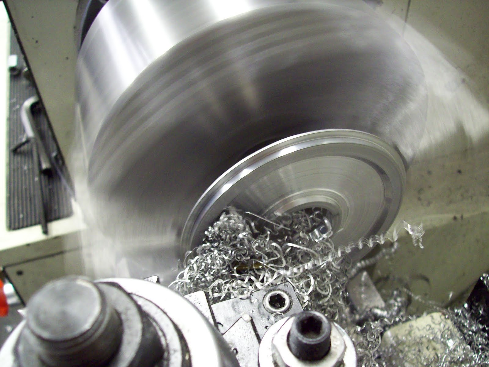
So this time, I decided to apply some angular principles of self-centering. I angled the bore by using a countersink bit. Furthermore, I grabbed the appropriate flat screws for the duty and a hexagonal standoff for the opposite end. It basically worked like V-groove stands for machining tubes. The round object is guaranteed to sit in the center of the groove. Works similarly for the conical shape. This method returned a much truer endcap, and validates the technique.


Also, automatic feeds are AMAZING. Almost a mirror finish. Never before have I turned such a smooth part.


I was only able to finish one end before the term ended, so there is no way I will be able to test the wheelmotor this summer. What I can do, is wind the stator. More on that in about 12-14 weeks.

In other news, I'm finally going to fight robots again! Dreadfully Wicked Robots is hosting PA Bot Blast in the Bloomsberg Mall. Features robots from 150 grams to 6 pounds. Heavens know I don't have a 6lber, but I do have the insect fleet.

I will be taking DDT, Cake, and P150.

Wait, p150? isn't he dead? Yeah, kind of. But he can be rebuilt... better... faster... stronger...


...and more carbon-y. Seriously, lets use some of these resources I have at the Invention Studio to make some grade-A bots. P150v4 uses the old 7.4, 300mah lipoly and Jeti advance 4 esc but everything else is new. 30:1 micro sanyos, Turnigy 2204 brushless motor, HMC 3-9 single channel escs, and Spektrum AR-2 gram receiver.


Waterjetted the carbon fiber plates. Surprisingly I didnt have to use fodder plates to prevent the delamination. I just used a large lead-in, and low-pressure settings. There was some delam happening around the frame, but nothing superduper glue could fill in.


I had a moment of boredom while it was raining and decided to try engraving on Carbon Fiber. It won't cut but instead seems to melt the epoxy a bit. I guess an experience not to be repeated.


Wiring the beast is hell. I made a minor design change on the fly. Originally the robot was to use .5" standoffs to space the innards, but I opted for .375" because the motor would have required a massive hub to make up the height deficit. As a result, everything was 2x crammed in the fuselage. I had to buy the spektrum AR-whatever 2 gram receiver with the micro JST plugs to make it fit.


STILL I had to remove the micro JSTs and direct solder. [note to users: spektrum decided to be crafty and switched the positions of the 5v+ and gnd on this receiver. BE WARNED]

The HMC3-9's were angled (WTF) and flipped to fit. Only one superbus was used for power.

Somehow, it all fit.


After turning down the wheels from 1.5" to 1.125", I finished the bore on some old Vrogy blades Seth Carr of Team Lab Rat graciously donated/sold cheaply.


Bam. A robot. I added and bent some strips of grade-5 titanium to bring it up to weight and add protection. It looks very similar to Wazio's Pookie if anyone remembers that being built. Eitherway, it performs like a champ. Gryos like crazy, quicker than any version of P150, can rip through 1/32" steel like frozen butter.

Minor tune ups were made to the other robots as necessary. DDT required no additional servicing (as usual), Cake was lubricated and modified to include mechanical locks on the drum shaft instead of set screws (because setscrews suck), and P150 was rebuilt as noted above. I am concerned for the needle roller bearings in Cake because I was unable to remake the shaft so there is some audible play in the shaft. Could damage the rollers, so I'll bring the old drum as a back up.

PA Bot Blast on July. Cheers!

Also, Cheesecake.

Thursday, March 24, 2011

p0w3r Drive: Cut.

Mad rush to get the wheel spinning before Spring Break. It is Spring Break now, was I successful?

...haha.

First operation was machining of the endcaps as discussed in the previous post.


Mounted to the lathe through a 5/16-18 cap screw and a copious number of hex nuts. Spun counter-clockwise at about 200 rpms for something that large in diameter.


Resulting part. Pretty shiny on all surfaces touched by the cutter. I did notice some wobble produced from radial play between the cap screw and the inner bore of the plate. This must have been what Shane was talking about. We will see if this proved troublesome enough to require correction, but considering the history of this project (v1 - v2 rebuild), I'll probably end up making new ones out of frustration.


The build is progressing very well so far! All components considered, it weighs just over two pounds, which is 2x lighter than the current kollemorgen system on my scooter. Speaking of which...

Stupid things to do on an electric scooter:


Part 2 to follow.

Sunday, March 13, 2011

p0w3r Drive: Sexy Things that Spin

Believe it or not, but I am halfway through revision 2 of the hubmotor. You ask, "what happened to the first version?"

Simple answer: I got lazy and the aesthetics bothered me. I mean, the motor was 1.625" wide, with only 1" of filleted tread. The 1/4" endcaps looked bulky and unattractive but I couldn't add an edge chamfer because the inner diameter features were already finished. Additionally, I neglected to add sufficient wiggle gap to the magnet ring rings, which made it extremely difficult to get the magnets in place. One formerly excited afternoon transformed into a painfully disappointing sanding feat. Once I had ONE magnet in the spacers, I knew that this was not worth the effort.

So with all these changes to be implemented, I elected to simply not finish version 1. Here is version 2: incredibly badass and sexy.


The wheel is now only 1.25" wide, with a 1.5" hubshaft (more wire space, finally!). I will still be using 1/4" endcaps, but I will turn down the edges and internal features so I can sink the endcaps further into the wheel. This also allows me to rid of the polycarbonate spacers, which served no purpose whatsoever. The mechanical lock nubs were replaced with precision eyeball machining aka I will be relying on a frictional fit from the endcaps and the OD of the magnet ring. This might seem like a bad idea, but It is better than trying to use 4-40's to lock the wheel and any slipping might act as a neat clutch feature. I also added .016" of space to the magnet gap so the magnets just drop in. No file work required.

To make the endcap features, I will be adopting a trick I learned from Shane Colton. First, machining will begin with a waterjet rough circle cut. A severely undersized internal bore and the seven through-bolt holes made. The bore will have a capscrew through it, accompanied with several nuts. These nuts will then be clamped in the chuck of the lathe, and all outer features will be finished. Thereafter, the bolts will be removed, and the bore will be opened with a boring bar. More work certainly, but I expect a much finer product.

Monday, February 21, 2011

p0w3r Drive: Three Cheers for the Arbor Press

Expecting to do some research this afternoon; did not exactly pan out. So I elected to say on west campus and do some wheel work.

The other night I tried boring one of the 5" 30A durometer wheels..


... but then it exploded. Synopsis tells me there are air pockets in the core material, and my feed rate was too high, which caused the bit to grab and toss the wheel. 300 fine for aluminum, not so much for plastic

Today, I went for round two. Turned the lathe into high gear, 455 rpms and lots of non-cinnamon (unfortunately) Tap-Magic. Like magic, we now has a properly bore'd wheel.


Posing with the stator for comparison.


Speaking of which, I put the stator hub back on the lathe and reduced part of the center mass. This would make internal wire organization easier by allowing more internal wiggle room.

Decided to tackle the flats next. Unable to find the binding screw for the large Vertrax mill, I went over to the ME2110 labs to barrow their cute mini mills.

OH GOD THE STORIES ARE TRUE! These mills really suck. I was making passes through aluminum like a pro, when I realized the mill axis started drifting. I felt like a inverted pendulum balancing robot, constantly adjusting to changes in my environment.


Either way, I finished the task, and with a half decent finish as well. Next chance I get, I'm asking my fellow studio ULI's how to tighten the collets on the Vertrax.

While I added a roll pin groove using a hacksaw, I finished preparing the waterjet, post-dredging. I want to say it would take about an hour to fill the tank manually, but since I filled it over the span of two days, nobody remembers. Similar is to be said about the number of licks it takes to get to the center of a Tootsie Pop.

Waterjet filled, cutting commences. I cut the magnet ring laminations from a 1/4" plate of A-36 mild steel, end caps from 1/4" 6061 Aluminum, and the spacers from 1/8" polycarbonate.


Ironically, the material for the spacers was the sheet of polycarbonate that was stolen from me last semester. Hmmm, how circular.

There was drilling, tapping, countersinking, and a big hand from the enormous arbor press. I declare the hubmotor mechanically complete. That leaves us in this current state:


Gathering inspiration from Iron man 2, I proceeded to wind the motor. 23.5 turns of wire per tooth, dLRK style for space savings.

Lesson learned: If you wind with anything 20ga or lower, wear gloves or wrap cloth tape around your fingers. Your writing hand will thank me later.


Completed stator winding, terminated with a Wye connection. I'll wait to see if this motor actually works before adding the sensors. This means the possible run date is the 23rd of Feb, seeing as how UPS managed to butcher the shipping of the box of magnets (routing delays).

Until then, cheers.

Saturday, February 19, 2011

p0w3r Drive: Turning

Late Friday night, looking to build. Waterjet is under its scheduled maintenance, so I elected to roll on over to the lathe for some quality turning time.

Feeling too frugal to purchase a large piece of Aluminum round, I pulled out a 1.25" dia round of 6061 from my scraps. Slightly less than 32mm. Shouldn't affect the system too much. I may add some anti-static tape to fill the gaps if necessary.


Post-Turn part. Drilled through with a 7/32" and tapped to 1/4-20. Chamfers with whatever degree I could find were made on outer edges. I was surprised to find a beautiful mirror-like sheen for the finish. Too bad that won't last long.


As illustrated in the model in a previous post, the ball bearing goes over that extrusion.


Radial picturage.

Next time when I finish prepping the waterjet, Ill cut the endcaps and the magnet can.

Speaking of magnet can, I elected to make a small design change in favor of using more (than one) of the 25ct bag of 2mm roll pins I bought. So here we have 7 additional 2mm holes through the magnet can rings as alignment devices.


I will probably partially press the rings together, add a gratuitous amount of superglue and press the entire assembly together. Should be solid. This part should NEVER BE SEPARATED!

Already I am beginning to find some slight design oversights. A 1/2" shaft with a 1/4-20 tap was a poor decision because that leaves very little room for wires to exit. Think of it as a 1/2" tube with 1/8" wall. My options are to make flats on three sides of the shaft or increase wire gauge. I am favoring the latter because cable organization would be far easier. I should be within reasonable current ratings in normal scenarios.

Friday, February 18, 2011

Hububububble Motor

The next logical step for any piece of technology is to make it lighter, more powerful, and smaller. These goals I hope to find in the first actual hub motor I will be building.

Don;t get me wrong, I have built my own brushless motors before. In fact, if anyone recalls the first Attrition, it had a custom built 40mm motor to internally spin the drum. Now it is time to build yet another motor, slimmer, larger in diameter, and torquier (new word or sp?).

First round will be a test platform. I have a bunch of ideas on improving the sea of hub motor designs but those will be applied once I can prove to myself that I can produce one basic device.


Borrowing the techniques of Shane Colton and Charles Guan, this motor will have the following characteristics:
  1. Flux ring is composed of waterjet stacked laminations. It will feature internal grooves to make magnet housing easier.
  2. Stator hub is a single piece turned aluminum round. It will have milled flats on both ends to facilitate the exit of motor and sensor wires.
  3. The motor will have three hall effect sensors to interface with the controller
  4. Motor will be wound 30-turns per tooth, dLRK for space savings
  5. 5" OD, 1.5" wide
  6. 70mm x 16mm Hitachi Stator
Where did I get these numbers from? Charles wrote up a neat instructable with will teach you motor building basics and some sample calculations for rough estimates. Very useful and highly recommended.

Instead of featuring threads to grip a tire, I will be using a "keyway" integrated into the flux ring.


In actuality, it is an extension of the through holes used to bolt the entire motor together. I sunk in the material where there were no screws, and left the extrusions as mechanical "grips" to grooves I will be adding to the inner diameter of the cored out 5" wheel. Forces are in the correct direction, I dont expect anything pushing the motor horizontally, this should work. The number of screws might change depending on how unsafe I feel about the sheer forces on 6-32 screws.


The pile of parts has already begun. McMaster-Carr arrived today, so I received two 30A durometer 5" wheels, three 1/2" bore ball bearings, and 2mm roll pins. I already salvaged the stator from an earlier grab, and the magnet wire recycled from previous orders. The bag of 6-32 flat screws came from Cake, where I ordered a bag of 50 only to use 2. Gotta love bulk buys.

The remainder of the parts should be coming in throughout the week/weekend. Speedy Metals is expected to arrive tomorrow, which means I can begin waterjet cutting the flux rings granted the machine is not broken (oh no my baby!). I suppose then it is possible to have a rotating wheel by Saturday morning. The Applied Magnetics order is projected to arrive Monday, but gluing magnets was never a time consuming issue since it is just adding glue. I don't need to be watching the grass to know that is growing.

For the time being, project name sits at "Power Drive", or "p0w3r Drive" if you are feeling creative.