Showing posts with label Cake. Show all posts

Wednesday, March 7, 2012

Return of the Roboteer

After exploding over $160 in brushless ESCs, I've decided to take a break from electric vehicles for the time being and get back to the finer points of combat robotics. Last year I had begun the development of a nifty angle-armor design with an eggbeater for a weapon. I tried to utilize the full capabilities of the Invention Studio, but I realize now I was missing the mark in design. So with that said, a few modifications:


In light of my new fondness for systems controls, this new version will be called "Dominant Mode".

New design features include:

  • Center support wall now used tabs instead of slots. # of screws reduced from two to one. This change added alignment benefits and more supporting material. The original design used only slots which meant the vertical misalignment was possible if the end-drilled holes were not exact. Using only one screw leaves more 2024 Al frame rail.
  • No more b16 gearmotors! While I am still using the indirect drive method (dual belts), I dropped the custom B16 gearboxes because the tolerances were too tight. Instead, I created a frankenbox from B16 motors (reasonable KV but high KT) with the "Ebay motors" gearboxes (10:1 ratio). With 15k rpms at 12v on a 10:1 gearbox, I should be getting 1850 rpms at each wheel at 14.8v. That is  FAST!
  • New drum design. That right, I said drum. Even with the 8+ hours of machining that block of A2 for the eggbeater, I just cant ignore the benefits of the drum. More difficult to make, but stronger overall, higher MOI, and more geometrically effective against vertical disks. It also allows me to experiment with my new drum design, detailed below.
  • No more Scorpion HX. Unfortunately not everything can become a positive. Due to bad dimension spec's by turnigy, I no longer have space in the robot for my scorpion HX. My alternatives are using the BB3-9 ESCs or the HMC 3-9 ESCs. While essentially the same, one doesnt suffer from transient neutral zone drift...
So once again I began building without documenting my steps (building gets too exciting to grab a camera, ugg).


Began by machining my wheels. That is .75" dia case hardened Al shaft wit ha groove for my urethane belts and a 3/8" bore for my bushings. A 1/4" dowel pin will press into my main frame rails and act as shafting for these guys. Like so:


Pretty sweet eh? I might be able to drive it soon! The urethane belts were custom made using cord stock from mcmaster-carr. Just hold the ends over an open flame and push them together. Removing from flame, the urethane will cool and fuse together. Then clip off the excess.


The actual tread come from a 3/8" sheet of 60A durometer SBR rubber. WATERJET GO!

A nice little feature to mention about the new frame rails are the tabs for the top and bottom plate. Additional rigidity and no quirky misalignment. Perfect every time! Here are the top and bottom plates:


The black plate is the top made from anodized 5052 Al and the bottom plate is 7075 Al (nothing but the good stuff!). Both are approximately 1/32" thick. I am really looking forward to engraving on the top. I'll pick some rather aggressive exponential to drive the "Dominant Mode" point.


On the bot

Over the weekend, I took the liberty of wiring up the robot. Knowing how little space I had remaining, I ended up with the electronics cube.


The bus caps on the weapon esc actually had to be resoldered to the board in a strange parallel combination. I had a chance to try my p0w3r bus idea again with the escs. The entire assembly is stuff! 10 points to the person who can find my receiver.


In the bot. I later surrounded all the surfaces with foam padding. ESD of course.

So some of you may be wondering, what will happen to that champion bot Cake? Well since I didn't end up using my B16's, scorpion HX, orange RXs, or my TP 3s 800mAH lipoly, I could very well reassemble! But with a special modification...


Muahahaha...

Next time, videos of driving and drum components build!


Friday, October 14, 2011

This is the Remix

I actually began toying with this idea awhile back, but since Cake's drums have become worn I figured it was time to try it out.


The integrated brushless eggbeater.

I've generally kept away from it because the internals are essentially open and thus vulnerable to a direct hit. To ensure safety of my motor and electronics, the beater must spin fast and never stop. Those two terms became the primary focus points in a new revision of Cake, which I might end up giving a new name as there are enough changes to warrant a new design.

Besides, I could never supply a very good explanation of why it is named Cake. I guess that rules out Cupcake as a possible name.

I bought a new motor and battery from Hobbyking. A Turnigy 1450kv motor of the same stator size coupled with a 4-cell 1000mAh lipoly. This is a 350kv increase in motor, and 3.7v, 200mAh increase in battery spec. Expect longer runtimes and higher end rpms. No load (unrealistic) of ~21k rpms! Most other spinning weapons sit around 10k - 15k range, so I have no doubt I'll be spinning quicker than them. The exception of course are Gene and Richard's creations (~49k rpms?) so I'll have to design a strategy to fight those.


Here is the model. Already I am beginning to like this design because it addresses some of the complications I have found with the drum design. First, there are no endcaps. The beater is machined from a single piece of A2 tool steel, and thus has its endcaps permanently fixed to the knockers. Assembly of the motor will be more complex certainly, but I think the benefits outweigh the complications.


I hope to never need to machine another beater ever again. First, I rough cut the 1" block of steel on the waterjet leaving .01" on all edges. Then, I moved the block to the manual mill, squared all the edges,and removed the extra .01". Finally, I faced the beater. All operations probably totaled to 12 hours of work.

Worst yet, I managed to make 3 mistakes on the part. Good thing I am such a improvising badass. Can you spot the mistakes?


Rapid prototyping the magnet can mount. I blame Charles for this recent fascination in 3D printing. And before you ask, the answer is no. That part will not remain extruded ABS.


Speaking of rapid prototyping, what exactly are these?


These are the next set of bad ideas in this revision: Angled armor plates and isolated but integrated frame gearmotors. These ideas I've been designing since Attrition but never had the resources to implement it. Times ave changed. While the Dimension spat out the can mount, I had the uPrint mush out the angled mating blocks. The current plan is the remake them from aluminum but I have no patience and wanted to see it all together.


Bingo! Geometry test pass!

My next goals are to complete the drive system. Some minor complications for the moment: The battery supplied from Hobbyking is just a few unforeseen millimeters too wide. As a result, my Scorpion HX speed controller does not fit as intended. I may need to reinvest in single motor controllers and utilize the 45 degree drive method (Sans mixing). I've also noticed a large amount of frictional binding when the gearboxes are populated. Closer inspection showed the holes to be drilled at a slight angle. UGH! Should I continue with the B16 mod, I will have to bore out the holes to 9mm ON THE MILL for some flanged shielded ball bearings with a 4mm bore. Other alternatives are modifying the "1000 rpm motors" that everyone has been hyping about. I bought a pair (to arrive next week) and plan on swapping the motors out to the lower current drawing KW motors that normally come stock on the B16's.

Monday, September 5, 2011

Dragon Con Bot Blitz

Dragon Con is (technically) still going on, and Robot Battles microbattles was yesterday. I already planned on bringing Cake and DDT, but Charles, Xo, Aaron, and I decided a fleet of "Assbots" were in order. By this time it was Friday the 2nd. Isn't Robot Battles on Sunday?

Charles was nice enough to donate an old Pop Quiz frame with some motors still attached. Remove weapon motor, blade, receiver and escs, as well as one motor. Three drive motors, a sturdy frame, and a dead 4-cell lipoly. This could work.

I left my shop camera at the apartment, but the result was pretty clear.


Introducing, Prop Quiz 0.5: waaaay too light.

Seriously, that is a 3 blade prop designed for baby helichoppers. Does it fly?


YES.

Unfortunately, it had some issues expressing flight in practice.


Xo and Aaron designed a melty style robot, where the entire frame rotates to give a 100% weapon mass.


And this is how that venture went:


Looks like it would have been pretty dangerous if it was made of metal or plastic and NOT WOOD. Seriously, the only piece of material we could find Saturday evening was a 3/4" block of wood. We decided to waterjet a pocketed frame that housed all the electronics. It also weighed approximately 1lb,5oz for a 3 pound class. I just wished it had hit the opponent instead of the wall.


And here is Charles' assbot, "$20,000 per year Enjeering Degree". Of course, the robot is in the arena, not the person on the left.


A resurrected sumobot back when speed hacked servos were still valid methods of power transmission. It also had a fair number of trinkets and symbolism: "the hand is symbolic of begging for money and the weight of student loans; the duct tape wrapped around the galvanized roof flashing is representative of the challenges students face in pursuit of fulfilling their engineering degree requirements; the threaded rod represents front-end ballast mass."

The serious business robots put on a great show as usual. DDT threw robot guts all about the arena and Cake probably threw a roof shot or two. Both robots were removed by Thomas Kenny's robots, who are great in design and quick as usual. The flaws in my robots were the same as usual, and I'll probably not fix them as well.

[rumble video]

So what's next? This upcoming Saturday is the Mini Maker Fair hosted by our very own Georgia Tech Invention Studio/Maker's Club. This means this week will be yet another hectic blitz to put together the scooter I hope to feature along with Charles' equipment. Be there if you can! We promise over 60 different exhibitors, a far greater turnout than expected.

Tuesday, August 16, 2011

Busy on Holiday

I'm currently on my two weeks holiday between work and institute but I'm kept relatively busy by upcoming events. Dragon Con and the Georgia Tech Mini Maker Faire are both coming up, which means I have about 5-6 things I need to get done.

Robots:
Running the bots at PA Bot Blast was a good way to test their metal against some real north east powerhouses but now I am left with no satisfactory running robots. Dragon Con doesn't run the 150 gram classes, but I still like to make a showing with an ant, beetle, and maybe a macro-class robot this year. I should have enough extra frame parts to revive Cake (I want to rebuild!) but the drums are just so fucked up I don't see too much in point in it. I would like to bring something different from DDT. The main idea is to not spend any extra money so we'll see how that turns out.

Costume(?):
If I go to any of these conventions, I like to put a little extra into it by dressing as something and then saving it for Halloween. As awesome as Tony Stark is, I DO NOT want to recycle a costume past a year. Hell, multiple conventions was pushing it. Right now I am looking into something Matrixy but those long coats are really damn expensive...

On to the interesting parts...

Scooter:
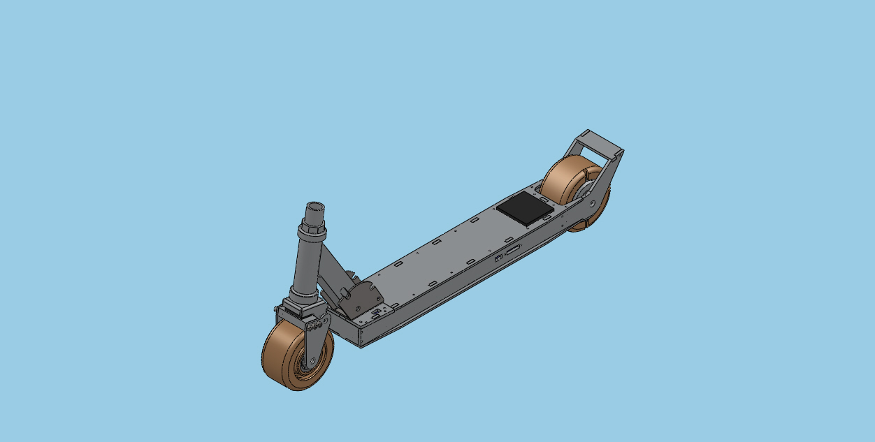
I bought this. Do I really need to state my intentions?


Safety Razor v1.1 is still in deployment, but I am putting foot down... on something other than concrete for braking. There are a few minor inconveniences in the current iteration that I am wanting to address in a new revision.
  • Braking - my left foot is unacceptable, and I just bought a pair of Nike shoes
  • Heft- At 13-15 pounds, the scooter weighs on the heavier side of objects. The motor alone weighs about 6 pounds, and the frame is unpocketed aluminum. All aspects of it (except the handlebars) are overspec'd.
  • Waterproof- it is not, and wetness has hurt it before
  • Switches - periodic replacement of switches due to destructive arcing is unacceptable. A precharge circuit is needed, or a high amperage switching method.
  • Longevity- last longer (she said that)
  • Smoother Rides- make it suck less when I hit cracks in the sidewalk
These are very realistic goals that all begin with the wheelmotor.

Weren't you building one already? Is it done yet? The answers to those questions are "yes" and "no". Since it isn't done yet, the logical thing would be to design another one.


In reality, I have an issue with leaving proper amounts of space for wires. I wish they were of infinitesimal thickness. Besides, that version was fitted to a 5" wheel, and as my calculations show, I can get a more efficient package from a smaller diameter but wider wheel (assuming stator also follows).


The new wheelmotor plan has lots of space for wires to route (over 1/4" of room) and a beefy 3/4" shaft for the passage of wires. The stator comes from a Turnigy motor, has a diameter of 52mm, and a length of 30mm. The stator will be wound dLRK with ~25 winds per tooth. Each magnetic pole is composed of two N52 neodymium bar magnets. All of this will be captive in a 4" rubber wheel of 40A durometer. Air gap is currently 0.6mm ideal.


To make this motor comparable to the 400W Kollemorgen , I will be routing sensors through the motor. A tad bit of trial/error is involved because I am planning on using a 150A RC car esc to drive it. Thanks to Charles and Shane, I have the pinouts of the sensor cables but I'll still be playing the mix 'n match game to determine the "A", "B", "C" motor terminals.


As a result of the motor swap, the entire frame gets a redux. The frame rails are still Aluminum but only 19" long now, and 3/16" thick instead of 1/4" before. In fact, all 1/4" plate is changed to 3/16". The top and bottom plates are still 1/8" Al, but there is no longer a garolite fancy cover plate. Instead, I am going to try engraving on some skater's grip tape and stick that to the aluminum. Also notice there are no T-nuts. All holes will be mill drilled and a silicon caulking will be applied to the inside corners to help with waterproofing.


Why don't I need the garolite cover anymore? All charge plugs are now externally accessible. A simple cover will go on top of those to prevent crud from getting inside.

What on earth is that monstrous black tumor protruding from the back? That is the model of the 150A esc. I don't actually have it on my persons yet.

Meanwhile, the battery was upgraded to a 6s1p 5000mAh lipoly pack. Super longpak!


A slight modification to the front forks to make it look less... awkward. This is the true advantage of the Razor A2 or A3 scooters.

For now, this will sit under the Safety Razor tag, but I am open to new names. Razor Wind?

Saturday, July 23, 2011

Last Week and Next Week (PA Bot Blast and Otakon)

Finally, a weekend where I am not rushing about to see new places or compete against other sentient beings. However I have stuffs to prepare for next week so after 7 hours of straight soldering, I elect to type up a post while I am still on a solder fume high (no not really).

Made the drive from Maryland to Pennsylvania for my first ever PA Bot Blast event! Driving up to Harrisburg in the wee hours of the morning but when I started up the road to Bloomsburg things sudden looked very hilly and untouched. Towns built into the valleys of the massive hills, which were covered with trees; to be honest I felt like I was in a northeastern Costa Rica. 7 halves hours later I arrived at the Columbia Mall and prepared to set up.

I brought P150, DDT, and Cake to represent the south. I hadn't really run these robots since April, so I assumed they were in working order. Boy was I in for disappointment. P150 and DDT both went 1W:2L for seemingly dumb reasons. They both lost wheels in their first matches. P150's was removed by hedgehog's angled cutter (and P150's poor control), and DDT's seem to have fallen off by chance (when Fangus and DDT hit, he popped the belt off the pulley, jamming the blade and spinning the robot, which threw the wheel off. If Fangus was the cause, my shaft would be missing). They then proceeded to defeat robots in their expected fashion only to lose again disappointingly. Some additional thought needs to be put into these robots.

Cake made a wonderful representation! 4 wins and 2 losses, both losses caused by One Fierce Lawn Boy from Fierce Robots. Every match ending up in KO. Videos below.


The money shot of the event. The final hit between Ripto and Cake in the loser's finals match resulted in Ripto being lodged between the lexan and the outer barrier. Ouch.


Jeremy ran a very professional event. Organized procedures, match listings, and even had clarifications for the grey areas of robotic combat. Needless to say, I'll be returning if I am in the area again!

PA Bot Blast 2011 Album


Next week will be Otakon, the largely anime convention in the Baltimore area. Now, I am not a huge fan of anime, but I do like to create. I had my Tony Stark, Iron Man costume shipped up to me during Independence Day break so I could work on it. A few upgrades ensued.

First I decided to add a blue tint to my LEDs. Feeling resourceful, I merely took a marker and drew on the outer surface. Nothing fancy.


The other upgrades were all for my sanity. I redid the wiring to be much more robust and clean. At Dragon Con, I had several problems with connections breaking and repairs required. This time, all solder joints were solid, shrinkwrapped, and glued.

Sunday, May 15, 2011

Supermassive Updates

I neglected updating the blog for awhile due to life, but I promise this post has some good content. First, the summary:
  • P0w3r Drive
  • PA Bot Blast Preparations
Last time I assembled the endcaps to find they were wobbly by not-so infinitesimal amounts. Did I re-machine them? You bet. But this time I implemented a different technique.

You might recall, the technique I have been using to machine the endcaps was to first rough cut a disk of aluminum on the waterjet and then turn the parts on the lathe using a socket cap bolt through the center. I believed the source of the issue same from wiggle room between the starting bore in the waterjet plate and the OD of the bolt (since drill bits increase in discrete amounts not necessarily tuned to bold diameters).

So this time, I decided to apply some angular principles of self-centering. I angled the bore by using a countersink bit. Furthermore, I grabbed the appropriate flat screws for the duty and a hexagonal standoff for the opposite end. It basically worked like V-groove stands for machining tubes. The round object is guaranteed to sit in the center of the groove. Works similarly for the conical shape. This method returned a much truer endcap, and validates the technique.


Also, automatic feeds are AMAZING. Almost a mirror finish. Never before have I turned such a smooth part.


I was only able to finish one end before the term ended, so there is no way I will be able to test the wheelmotor this summer. What I can do, is wind the stator. More on that in about 12-14 weeks.

In other news, I'm finally going to fight robots again! Dreadfully Wicked Robots is hosting PA Bot Blast in the Bloomsberg Mall. Features robots from 150 grams to 6 pounds. Heavens know I don't have a 6lber, but I do have the insect fleet.

I will be taking DDT, Cake, and P150.

Wait, p150? isn't he dead? Yeah, kind of. But he can be rebuilt... better... faster... stronger...


...and more carbon-y. Seriously, lets use some of these resources I have at the Invention Studio to make some grade-A bots. P150v4 uses the old 7.4, 300mah lipoly and Jeti advance 4 esc but everything else is new. 30:1 micro sanyos, Turnigy 2204 brushless motor, HMC 3-9 single channel escs, and Spektrum AR-2 gram receiver.


Waterjetted the carbon fiber plates. Surprisingly I didnt have to use fodder plates to prevent the delamination. I just used a large lead-in, and low-pressure settings. There was some delam happening around the frame, but nothing superduper glue could fill in.


I had a moment of boredom while it was raining and decided to try engraving on Carbon Fiber. It won't cut but instead seems to melt the epoxy a bit. I guess an experience not to be repeated.


Wiring the beast is hell. I made a minor design change on the fly. Originally the robot was to use .5" standoffs to space the innards, but I opted for .375" because the motor would have required a massive hub to make up the height deficit. As a result, everything was 2x crammed in the fuselage. I had to buy the spektrum AR-whatever 2 gram receiver with the micro JST plugs to make it fit.


STILL I had to remove the micro JSTs and direct solder. [note to users: spektrum decided to be crafty and switched the positions of the 5v+ and gnd on this receiver. BE WARNED]

The HMC3-9's were angled (WTF) and flipped to fit. Only one superbus was used for power.

Somehow, it all fit.


After turning down the wheels from 1.5" to 1.125", I finished the bore on some old Vrogy blades Seth Carr of Team Lab Rat graciously donated/sold cheaply.


Bam. A robot. I added and bent some strips of grade-5 titanium to bring it up to weight and add protection. It looks very similar to Wazio's Pookie if anyone remembers that being built. Eitherway, it performs like a champ. Gryos like crazy, quicker than any version of P150, can rip through 1/32" steel like frozen butter.

Minor tune ups were made to the other robots as necessary. DDT required no additional servicing (as usual), Cake was lubricated and modified to include mechanical locks on the drum shaft instead of set screws (because setscrews suck), and P150 was rebuilt as noted above. I am concerned for the needle roller bearings in Cake because I was unable to remake the shaft so there is some audible play in the shaft. Could damage the rollers, so I'll bring the old drum as a back up.

PA Bot Blast on July. Cheers!

Also, Cheesecake.

Monday, January 10, 2011

Hot n Cold

By now I will be back at Tech. By now I should be starting to go to class. Instead I've been holed up in my residence because GT has shut down due to a flurry of snowfall last evening. It is pretty cold outside, but alas there is work to do: Cake's drive escs are getting too hot!

Seth at the Robot Marketplace recently informed me of a new set of KW motors for the B-series gearmotors. These guys pull more current, but are spec'd at 937 rpms at 12V or so. That is ~300 rpms over the old motors which will work great for my 1.5" drive wheels.

But if you ask me, it still feels slow compared to DDT. So lets take the motor mods a step further.

Tower Hobbies sells paired motors for direct drive foamies. 180 sized, high rpm, high current, and the correct shaft diameter. More importantly, they were on sale for a bulk buy!

The operation was a simple motor switch since the mounting patterns were the same.


Here the motors are installed with the B16 gearboxes. Ignore the new escs for the time being.
Months ago, I also purchased two scorpion mini escs to replace the damaged scorpion HX dual esc. You may recall, I had some SMT components fall off the board and while it has served me well my distrust is well placed. The two scorpion minis side by side fit perfectly horizontal in the electronics bay and open up much more room for the wires and plugs from the drum.


I applied a light application of glue on the edges to hold the two boards together, so that I could use breadboard jumper wires to bridge the main esc terminals like P0W3R busses.


Note how there are two plugs on the esc. One plug is actually for battery, but the other connects the the drum esc. Having the same connect with the same polarity makes for stupid proofing.

The real problem was that the new motors drew more current than the escs could handle. Evaluating my options, I felt that adding heatsinks was a far easier solution than disabling current limiting or upgrading the FETs. I cut some blocks of 1/8" thick copper bar (back when copper was not ass expensive) and tapped some 4-40 threads to facilitate mounting to the FETs.


A light application of silicon based heatsinking compound helps heat transfer between the materials. I also made a note to sand and polish the mating surfaces. Oxidation on the bar left lots of non-conduction crud on the outside.


Finally mounted we discover the robot to be significantly quicker, with extended runtime. I can achieve approximate 3 minutes of vigorous driving before the escs overtemp. This is acceptable.

Here is everything installed in the robot. The first picture of this post shows an unexpected benefit of adding the heatsinks. The board material fits right in between the header pins and the capacitor in my AR6110 receiver for optimal space savings!