Showing posts with label Safety Razor. Show all posts

Saturday, September 24, 2011

And We Shall Call it... Razor Wind

Last time we discussed the improvements over Safety Razor v1.1. Where are we now? Well in Atlanta Maker Faire build blitz, I built the entire thing. Lets see what images I can scrounge up.

Seeing as how there were 1-2 weeks until the event, I broke down construction into two main parts: frame and hubmotor. Ive attempted building a hubmotor several times, but never finished them. I'll be paying special attention to the motor this time.

First came the turning of the wheels. The front wheel included two facing operations and two counter boring operations for bearing recesses. The shaft was also turned from a round of 1-5/8" billet.


A stator was salvaged from a Turnigy motor. It measures 52.84mm in diameter and is planned for about 20-25 turns a tooth as described in the last post. The shaft was machined by our resident expert machinist Stephen Culpepper. A light application of glue held the motor in place.


Ever since I learned how to properly set my working zeros, my parts have come out drastically more precise with better finishes. The endcaps were First waterjet machined from 5/8" plate and then turned on the lathe. While mounting the plate on the cutting table, I realized I ordered 3" wide flat for a 3" dia part. 


Luckily, I am a boss. The advantage of waterjet cutting first allows me to add through holes and a tentative bore. This way, I wont have to mount the disks on a rotary table to drill the holes. 


Magnets installed. Each strip is actually composed of two magnets for a total of 28 magnets. It works, but is irritating for slow settling glue because the field on the edges repel each other.


I also spent this moment to waterjet the magnet flux rings. These were cut from 1/2" A-36 plate, epoxied together to make a total stack of 1.5". Anyway, back to the endcaps.


Partway complete.


These are probably the best pieces I have turned in my entire robotics career. The only surface I wish I could have treated were the outer edges of the flange as it still has the water jet's frosted edge.


Two endcaps with bearings were press fit in the bore of the wheel. Inside lay the waterjet style flux rings. A waterjet scrap of 3/32" polycarbonate served as a sensor mount. I figured this convenient in case I wanted to manually advance the timing of the motor.


Glued...


Wired...


Installed.

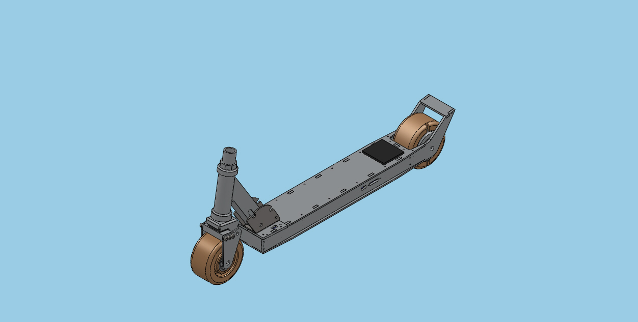
The rather large and wide front wheel of the scooter would need a custom set of front forks to account for the 2x width. Luckily, the Razor A2 frame has a "shock mounted front" aka block of rubber and hinge. I took this opportunity to create a custom mating piece that has shock absorption and a wider section. 


A block of aluminum was first water jet machined to rough dimensions and finished on the mill. The raised section in the back limits the backwards travel of the hinge, the 5/16" hole is the hinge point, and the 10-32 tapped holes mate to parallel plates to facilitate the wheel.


The frame went together as quickly and easily as the old one did. This time I spent time to open up the width of all the slots by .005" such that I would have to do less sanding later. I also decreased the kerf compensation from .015 to .012 on the waterjet. The combination of both along with the use of a scrapper produced a very clean tabbing. I don't have to hammer anything together, but instead they press lightly together. The appropriate frame parts were mill mounted and drilled as needed. First a spot drill, and then a sharp 3/32 to finish it up.

Repeat. The frame at one point in time looked like this:


The main rails were together and it was beginning to take shape. A day later:


It looks much more sleek than Safety Razor. Looking at it, you could barely tell it was electrically assisted at all. Let's compare it to Safety Razor:


By late Friday evening before the Maker Faire, the lot of us grew lazy. I was intending to waterjet the throttle pieces from 1/4" Aluminum, but Charles convinced me to start rapid prototyping the remaining parts.


 Among the throttle, the fan covers and charge plug covers were also printed.


The final product! Now presenting Razor Wind!


So how did it work? Well it worked well for about 20 minutes before failures began. The main problem lay in the motor. The motor seemed under specified for the amount of load required. I decided to opt for 20 turns of 20ga wire because I wanted speed, originally thinking the speed controller could throw enough current to through the motor to meet the requirements dictated by the sensors. However, this caused the motor to heat up very quickly. The heat, combined with the motor torque broke the glue joints and allowed the motor to rotate around the shaft. This effectively ripped wires apart internally and shorted some connections. The motor went up before the Maker Faire.

Razor Wind still served as a great display item along with the still functional Safety Razor. We also had some surprise scooter-wielding guests.


I have since then rewound the motor with 22ga wire and machined a small nail to act as a roll pin for mechanical locking. I am convinced the real solution would be to increase the voltage or overall size of the motor. My next solution, involves some number of these:


Tuesday, August 16, 2011

Busy on Holiday

I'm currently on my two weeks holiday between work and institute but I'm kept relatively busy by upcoming events. Dragon Con and the Georgia Tech Mini Maker Faire are both coming up, which means I have about 5-6 things I need to get done.

Robots:
Running the bots at PA Bot Blast was a good way to test their metal against some real north east powerhouses but now I am left with no satisfactory running robots. Dragon Con doesn't run the 150 gram classes, but I still like to make a showing with an ant, beetle, and maybe a macro-class robot this year. I should have enough extra frame parts to revive Cake (I want to rebuild!) but the drums are just so fucked up I don't see too much in point in it. I would like to bring something different from DDT. The main idea is to not spend any extra money so we'll see how that turns out.

Costume(?):
If I go to any of these conventions, I like to put a little extra into it by dressing as something and then saving it for Halloween. As awesome as Tony Stark is, I DO NOT want to recycle a costume past a year. Hell, multiple conventions was pushing it. Right now I am looking into something Matrixy but those long coats are really damn expensive...

On to the interesting parts...

Scooter:
I bought this. Do I really need to state my intentions?


Safety Razor v1.1 is still in deployment, but I am putting foot down... on something other than concrete for braking. There are a few minor inconveniences in the current iteration that I am wanting to address in a new revision.
  • Braking - my left foot is unacceptable, and I just bought a pair of Nike shoes
  • Heft- At 13-15 pounds, the scooter weighs on the heavier side of objects. The motor alone weighs about 6 pounds, and the frame is unpocketed aluminum. All aspects of it (except the handlebars) are overspec'd.
  • Waterproof- it is not, and wetness has hurt it before
  • Switches - periodic replacement of switches due to destructive arcing is unacceptable. A precharge circuit is needed, or a high amperage switching method.
  • Longevity- last longer (she said that)
  • Smoother Rides- make it suck less when I hit cracks in the sidewalk
These are very realistic goals that all begin with the wheelmotor.

Weren't you building one already? Is it done yet? The answers to those questions are "yes" and "no". Since it isn't done yet, the logical thing would be to design another one.


In reality, I have an issue with leaving proper amounts of space for wires. I wish they were of infinitesimal thickness. Besides, that version was fitted to a 5" wheel, and as my calculations show, I can get a more efficient package from a smaller diameter but wider wheel (assuming stator also follows).


The new wheelmotor plan has lots of space for wires to route (over 1/4" of room) and a beefy 3/4" shaft for the passage of wires. The stator comes from a Turnigy motor, has a diameter of 52mm, and a length of 30mm. The stator will be wound dLRK with ~25 winds per tooth. Each magnetic pole is composed of two N52 neodymium bar magnets. All of this will be captive in a 4" rubber wheel of 40A durometer. Air gap is currently 0.6mm ideal.


To make this motor comparable to the 400W Kollemorgen , I will be routing sensors through the motor. A tad bit of trial/error is involved because I am planning on using a 150A RC car esc to drive it. Thanks to Charles and Shane, I have the pinouts of the sensor cables but I'll still be playing the mix 'n match game to determine the "A", "B", "C" motor terminals.


As a result of the motor swap, the entire frame gets a redux. The frame rails are still Aluminum but only 19" long now, and 3/16" thick instead of 1/4" before. In fact, all 1/4" plate is changed to 3/16". The top and bottom plates are still 1/8" Al, but there is no longer a garolite fancy cover plate. Instead, I am going to try engraving on some skater's grip tape and stick that to the aluminum. Also notice there are no T-nuts. All holes will be mill drilled and a silicon caulking will be applied to the inside corners to help with waterproofing.


Why don't I need the garolite cover anymore? All charge plugs are now externally accessible. A simple cover will go on top of those to prevent crud from getting inside.

What on earth is that monstrous black tumor protruding from the back? That is the model of the 150A esc. I don't actually have it on my persons yet.

Meanwhile, the battery was upgraded to a 6s1p 5000mAh lipoly pack. Super longpak!


A slight modification to the front forks to make it look less... awkward. This is the true advantage of the Razor A2 or A3 scooters.

For now, this will sit under the Safety Razor tag, but I am open to new names. Razor Wind?

Friday, February 18, 2011

Hububububble Motor

The next logical step for any piece of technology is to make it lighter, more powerful, and smaller. These goals I hope to find in the first actual hub motor I will be building.

Don;t get me wrong, I have built my own brushless motors before. In fact, if anyone recalls the first Attrition, it had a custom built 40mm motor to internally spin the drum. Now it is time to build yet another motor, slimmer, larger in diameter, and torquier (new word or sp?).

First round will be a test platform. I have a bunch of ideas on improving the sea of hub motor designs but those will be applied once I can prove to myself that I can produce one basic device.


Borrowing the techniques of Shane Colton and Charles Guan, this motor will have the following characteristics:
  1. Flux ring is composed of waterjet stacked laminations. It will feature internal grooves to make magnet housing easier.
  2. Stator hub is a single piece turned aluminum round. It will have milled flats on both ends to facilitate the exit of motor and sensor wires.
  3. The motor will have three hall effect sensors to interface with the controller
  4. Motor will be wound 30-turns per tooth, dLRK for space savings
  5. 5" OD, 1.5" wide
  6. 70mm x 16mm Hitachi Stator
Where did I get these numbers from? Charles wrote up a neat instructable with will teach you motor building basics and some sample calculations for rough estimates. Very useful and highly recommended.

Instead of featuring threads to grip a tire, I will be using a "keyway" integrated into the flux ring.


In actuality, it is an extension of the through holes used to bolt the entire motor together. I sunk in the material where there were no screws, and left the extrusions as mechanical "grips" to grooves I will be adding to the inner diameter of the cored out 5" wheel. Forces are in the correct direction, I dont expect anything pushing the motor horizontally, this should work. The number of screws might change depending on how unsafe I feel about the sheer forces on 6-32 screws.


The pile of parts has already begun. McMaster-Carr arrived today, so I received two 30A durometer 5" wheels, three 1/2" bore ball bearings, and 2mm roll pins. I already salvaged the stator from an earlier grab, and the magnet wire recycled from previous orders. The bag of 6-32 flat screws came from Cake, where I ordered a bag of 50 only to use 2. Gotta love bulk buys.

The remainder of the parts should be coming in throughout the week/weekend. Speedy Metals is expected to arrive tomorrow, which means I can begin waterjet cutting the flux rings granted the machine is not broken (oh no my baby!). I suppose then it is possible to have a rotating wheel by Saturday morning. The Applied Magnetics order is projected to arrive Monday, but gluing magnets was never a time consuming issue since it is just adding glue. I don't need to be watching the grass to know that is growing.

For the time being, project name sits at "Power Drive", or "p0w3r Drive" if you are feeling creative.

Thursday, January 6, 2011

Safety Razor Safety Advisory Report

So it's been a month since I butchered a child's Razor scooter and shoved a electric bike motor system into it. Let's hear some results!

I am able to use it for inter-campus transportation with about 50% capacity drain for a full day.


That's acceptable. Especially since it is probably mostly burst amps from accelerating. Voltage has yet to drop below nominal 22.2 (for a 6-cell lipoly). I still regularly monitor the pack for increased volume, but nothing vile has arisen. The picture above shows post-charge results. We have a 66% drain over an extended run time (I had group projects across campus that evening). You'll have to excuse my camera. No flash superimposed the words "END" and "BAL" to create the illusion of "BAD" on the LCD screen.

Over a period of time, I discovered my ground clearance to be steadily decreasing. My predictions have been reaffirmed. The amount of metal removed from the original frame, combined with the hastily designed frame extensions drastically reduced the integrity of the structure. I disassembled the frame this holiday break and discovered the fracture points to lay just as I had predicted: the region where aluminum and polycarbonate met.


All of this could have been avoided by starting with a single piece aluminum frame extension. Thankfully, I am still a ULI, and speedy metals is having a 10% holiday discount until January 31. Therefore, bring in the upgrades!


From the image, you can see the back end remains virtually the same. I rotated the motor mounting holes so that the centerline from the motor shaft to the wheel deadshaft were in line. Originally, the sprocket would rub against the spacer with left from some interestingly deep erosion marks as illustrated in the picture below. Undamaged spacer included for reference. I hope you know what a hex bolt is supposed to look like.


The majority of the changes were made to the front half. This iteration does away with the original scooter frame. It was far too troublesome modifying the frame to the design and it bore little fruit other than comedic value. This body is serious business. Slots and tabs everywhere. The accessible panel has been moved from the bottom to the top. This is because repeated ground scrapings sheered screw heads which made it a pain to disassemble. Speaking of bottom plates, a UHMW skid bar will be added to take the blunt of aggressive gutters and sidewalk ramps. On top of all that aluminum will most likely be a sheet of 1/16" garolite. Just something to cover the large gaping service channel and be pretty. If it is garo, I might even consider laser engraving a graphic into the center of the deck. Gettin' fancy now...

Of course, this frees up about 2-3" of space in the scooter body, not to mention the extended width and height. This means I can opt for a BIGGER BATTERY or protection to my current pack. Both would be nice, but I may push for the larger battery in preparation for the next advancement in campus transportation: MTD (to be described in detail later).

Lots of great material coming up (but its late, and im lazy).
-BBots
-MTD
-Hardbord

Saturday, December 11, 2010

I Added a Scooter to my Motor

Here's the story:

On Black Friday, I bought this Razor-A scooter for $17. Now why would I waste my money on a scooter built for 5 year-olds(+)?

So I could concatenate one of these with it:

That is a 24v, 400W Kollmorgen brushless sensored motor that weighs 5-6 lbs. It is made for electric bicycles and weighs more than the scooter frame. Finally, it is larger in diameter (~5") than the scooter wheels (98mm ~ 4").

Needless to say, this is a project of epic disproportions! Yet, I still want to be manageable so I can actually use it in my cross campus commutes. Here's the game plan:

I am going to make an extended under body to house the batteries and extend the length so I can have some foot space and motor mounting provisions. Tentative model:


The wheel will be chain driven (#25) at about a 2:1 ratio. The frame thickness about the body is 1.25". The spoiler on the back is not for down force but rather acts as a foot rest because the frame is so small (seriously, the frame can only fit one of my feet lengthwise). Everything has slots, T-nuts, and delicious waterjetting. This will require major frame modifications too. The rectangular extruded frame will need to be cut on the bottom to allow the battery to hide inside. Also, some of the flanges on the side will need to be cut off because I need a flat surface to bolt the aluminum plates. Each operation removes from the structural rigidity of the frame which worries me.

Now one decision I am regretting is making the front segment from 1/4" polycarbonate. Why on earth would I make such an important part from (thin) plastic? Well because I already had it on hand. I'm in college and money doesn't grow in trees. I am worried about it bending or snapping somewhere in that region. I would run FEA on the part, but I have no idea what grade of shit-luminum Razor uses on their scooter.


Lots of pretty parts. The front of the undercarriage is made already from pre-existing plates of polycarb. Longpack and Macromotor wait in the wings...


And here is the integrand. One razor scooter awaiting cosmetic surgery...

Anyway, A lot of building happened in the span of three days and magically the project is done! My phone actually ran out of batteries so I couldn't take any build pictures. :(

Sorry folks, all you get are end result pics and video!


Sitting pretty by my fridge(s).


The throttle is a 5k pot with a shaft hub from Servo City. I should enclose those wires sometime soon.


The rear module. You can tell it is slightly different from the original CAD because I had forgotten which direction the motor spun. This made for a very disappointing initial ride test.


Closeup of the slot and tab T-Nut design. I experimented with the tool offsets on the waterjet such that it is a perfect slide with higher quality cuts. Are you proud of me Charles?


The underside. Notice where the metal becomes polycarb. I expect this region to be first to fail because it sits in between the two wheels and theoretically supports the entire rider's weight.

It has more than enough power to flip a rider over and reaches a top speed of ~20mph (calculated as 3500rpm on a 98mm wheel). It is amazingly unsafe...

... so I shall call it, "Safety Razor"