Thursday, December 29, 2011

I Accidentally...

...my last urethane belt. Look at that snaggletooth.


As I began reassembling Razor Wind after cleaning it up, I neglected to check the motor direction before stepping outside for a test run. After the initial kick start, I threw the throttle only for it to instantaneously brake and change directions. Stripped all the teeth off.

Time to order the upgrades.

Also, I finally got the institute's mascot on my scooter. Been wanting this shot for years.


Sunday, December 25, 2011

Razor Wind: Shredding is a Pro for Guitarists, but not for Power Transmission

I've been running the Wheelpod system for about 3-4 weeks now and needless to say it has been an interesting experiment with pulley diameters and belt materials. I began with a 13T motor pulley, a 29T wheel pulley, and a 3/8" wide XL neoprene/fiberglass timing pulley. After a few runs, I noticed the drive producing extra grinding sounds and added a tensioner to absorb the thermally induced slack. Days later, the belt actually snapped.


All the teeth seemed to have rounded a bit (nominal trapezoidal shape) but the failure point was clear. The tension members all failed at one point, where the belt broke. At least I was in front of my apartment when it happened. Had I been at the Invention Studio, I might have been raging a bit.

So what happened? Easiest assumption is the wrong material. My second choice was a urethane belt, with kevlar tension member. Kevlar? HELLS YES! I also knew from experience that the urethane timing belts suffered less form expansion. I was hoping this combination alone would be able to solve my problems.

I did however have to change the motor pulley, because the Urethane belts came in intervals of 5 teeth (5 x .2" = 1" differences between belts) which meant I had to recalculate my belt distances. A new pulley with 11T was swapped for the 13T.

Can anyone guess what is going to happen next?

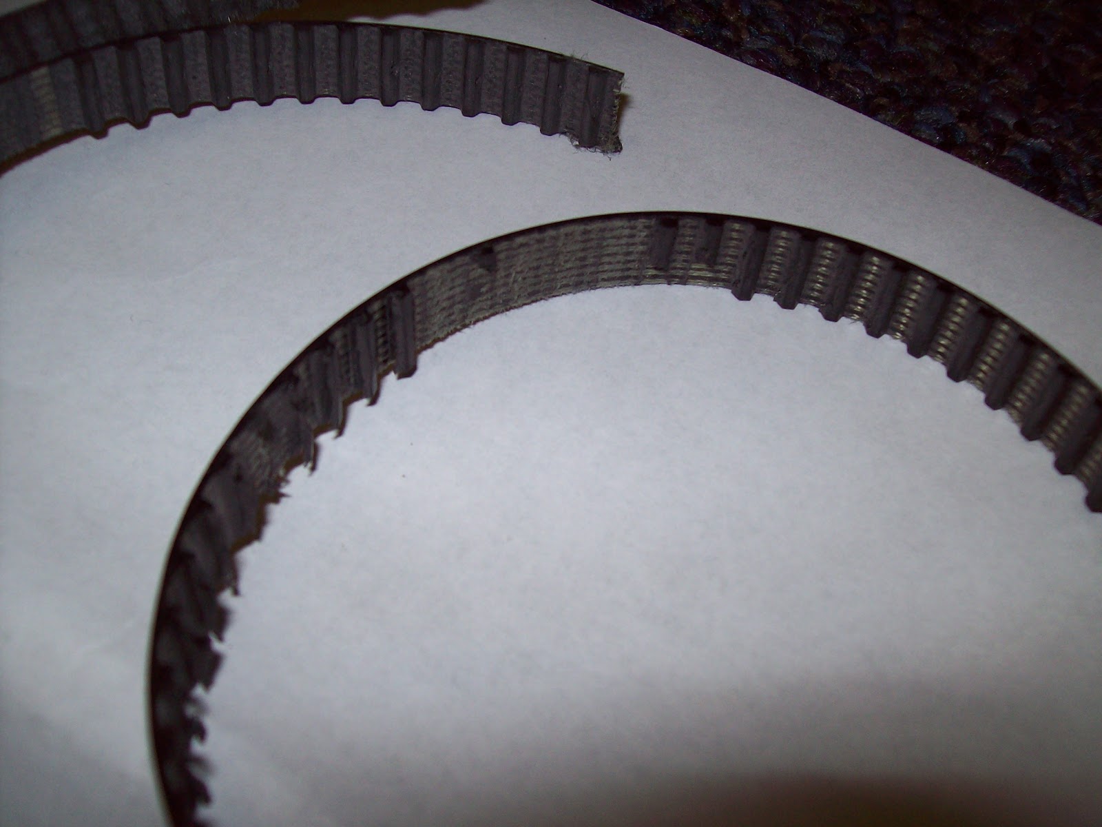
Well I blatantly ignored the minimum tooth requirement for most timing pulleys. Basically the number of teeth in contact with the motor pulley were not enough to resist the force required to move a human body at that ratio. Most (if not all the teeth) eventually sheered off like in the belt below.


And this belt too...


And this belt most recently. Luckily I had purchased enough belts to make it past my finals week (otherwise I would have surely been late to each one). The problem was clearly not belt or tension cord material. After consulting the problem from a few different angles I determined to cause to be the pulley diameter.


Increasing the pulley diameters (proportionally) would not change my overall ratio, but would allow a greater number of teeth in contact. This redistributes the sheer forces acting on each contact belt tooth.

While I was at it, I figured I would redesign the wheelpod chassis for 'real' belt lengths, and a dynamic belt tensioner.

However in the interest of saving time and material, I've elected to skip the experimental belt steps and revert to a method that has worked before: #25 chain. I will still be increasing the sprocket diameters to distribute the loads, but I will be using metal roller chain, which supports much higher working loads.

Starting with the largest motor side sprocket I could support and the center to center distance between the motor and wheel, I used this nifty chain length calculator to empirically determine a combination of chain and ratio that would suffice. The only limitations is that the sprocket tooth number and the # of chain links had to be integer values. In the end, I chose a 14T motor sprocket, 31T wheel sprocket, and a chain of 51 links. That gives an overall ratio higher than the current setup, but hell I know the motor can output enough power to make the scooter fly.

Machining to take place the moment I return to Tech. But until then, Happy Holidays!

Sunday, December 18, 2011

Razor Wind: Motorpod Edition

Shortly after the demonstration video shoot for the Clough Undergraduate Learning Commons, I burned out the version 1 wheelmotor. I knew the motor was running hot, I thought I had seen some sparks fly out the side, but I wasnt alarmed. Not until smoke billowed from the nearly air-tight electronics compartment was I actually worried.

Turns out some screws loosened, some wires shorted, and magnet wire combusted. Some serious weld marks were left inside my frame.

So I disassembled it and left it aside. I got pretty tired of fiddling with wheelmotors after rebuilding neumotor 2-3 times so I designed an alternate power system: The Wheelpod.

Behold!


A separate power drive system that easily slips into the space of the old one. This particular design slipped in between the two main frame rails and bolted/pivoted about the old wheel axle location. Mechanical tabs prevent the module from rotating in any undesirable direction. When a person stood on the scooter, the rotation about the pivot point applied a counter rotational force on the rear footrest spoiler and the from plate about the speed controller cover.

But what for drive? I spent a fair amount of time perusing the new line of Hobbything Turnigy SK3 motors when I realized Xo and I had one remaining unmodified Turnigy 6364-280 from Hardboard.

I never thought I would be reassembling one of those motors.

Some quick calculations: 280kv @ 22.2V, with 4" wheels and a ~2.2:1 belt ratio leaves about 30 MILES PER HOUR. YESSSSSSSSS!

The device went together about as quick as the waterjet could sneeze its watery sand snot.


Waterjet timing pulley using the low-taper cut settings to prevent belt deviations due to taper. The bore was turned to accept a giant-ass ball bearing. Eight holes run through the entire assembly to secure all parts.


 Wheels were also bored out. The preferred Colson 4" x 1.25" was selected because it offered the most thermoplastic core. The 1.5" and 2" wide versions has much more rubber and made turning difficult. For this design, I decided to enhance the rigidity of the wheel by adding aluminum plates to each side. This would give the bearings a better material to sit in and provide a more positive material to tap and thread.


The stack, not yet ready to be pressed in.


For some reason I managed to epically fail with hole placement. It did not occur to me the THRU diameter of #6 hardware, but I was left with this case regardless. So I did what any 'sensible' engineer would do and take a reamer to it. Don't hurt me too much.


The results were actually reasonable. It was very tight, but enough screws passed through to finish the piece. The way I see it, I have some potent 'thread locker' in this assembly. 


The protruding screws were screwed into the timing pulley above. After turning some spacers, boring out timing pulleys, and screwing stuff:


One thing I neglected to do was design the sensor module. As a result, it is currently running sensorless. While it is less a headache for me, I would like to someday add a data collection module in the scooter so I can produce REAL values for comparison. Someday...