Wednesday, May 8, 2013

Beyond Unboxing: Chinese E-bike Controller (chatparts.ltd)

This post is a preliminary to a much more comprehensive post detailing controller capability that will be made when I am nearby more legit diagnostic equipment. For now, this post will contain my conclusions from observation, use, and light modification.

The "Beyond Unboxing" series is inspired by Charles Guan's posts concerning these same type of escs.

The Thing:
I have purchased a marketed 24V, 250W brushless controller for e-bikes hopefully as a replacement for Jasontrollers. What caught my eye was the cheaper shipping, faster delivery time, and the seller whose English was grammatically correct. It arrived just yesterday and after some observations, I am very excited about this controller.


The seller even included pre-stripped connectors!


Its casing was a interesting trapezoidal feature. Still a single tube of extruded aluminum, still two silicon pads on either end captured by two stainless steel brackets. I even think they used the same screws...

The chatparts esc also has fewer wires. The seller includes a diagram of the connectors (without labeling the individual wires) but there are unfortunately more than 9 connectors on this controller.


In short, it is incomplete. However the function can be deciphers from the connector ends since these are meant to be direct drop-ins for existing EV systems.

The Comparison:
Now lets have a closer look at a jason and chatpart side by side.


Its smaller... Less thick by about 1/8"


Board looks less janky. The chatparts ESC (bottom) has only SMT components whereas the jason (top) does not. I was also intrigued by the 7 labeled vias at the top left of the esc (in this picture, in this orientation). Those look like programming pins. It may be possible to reverse engineer the software and find out REALLY how this guy works.


Again, fewer wires.


Ah the processor! Everything in here is ST Mirco stuff.

MOSFETs:   STP75NF75
Processor:     STM8S903K3

Performance:
My test rig is just my latest GigaRazor scooter (that none of you know about yet) with a watt meter inline with the power source. Note that this is a sensorless configuration. I will not be able to conclude as to what functions it has but I can at least detail its behaviors.

Unmodified Test runs:

  • No-load behavior: Ramps up until near max throttle where controller experiences cutoff. Not choppy intermittent behavior, simply cuts-off. Repeatable behavior. However does not affect throttle behavior for subsequent runs. Lets consider this feature Controller Protection.
  • Load behavior: ~20 Amps current limit stock. Does not experience high speed cutoff under load (perhaps I am not traveling quick enough to reach no-load speeds). ESC is cool to the touch.


The controller was then modified using the solder-blob shunt method.

Modified Test Runs:

  • No-load behavior: Experiences intermittent cutoff at higher speeds. It is choppy, unlike the unmodified behavior before.
  • Load behavior: increased acceleration as expected. Choppy behavior as described in no-load experienced in load behavior. Watt meter reads ~50 Amps peak. Case is hot.


The controller shunt was then lowered to 40A and then 35A afterwards. The choppy behavior still persisted. I took this opportunity to measure to case surface temperature and discovered it was in excess of 120 degrees F AFTER a run at higher current.

My scooter uses an 8s3p A123 LiFePO4 pack and a Turnigy Areodrive SK3 6374-149 motor. This means at nominal voltage I should be rotating ~3933 RPMs. However at charged voltage I would be ~4172 RPMs. For comparable controllers in this application, it exceeds the infamous RPM limit determined by Charles and Shane years ago. To validate the RPM limit cutoff, I will test no-load conditions again using a 24V nominal battery or PSU.

Conclusions:
I will withhold my final judgement until I can more easily explain its behaviors and features. For now I can summarize the main takeaways:


  • Runs sensorless (sensored TBD although it has wires for it)
  • Possibly has high eRPM controller protection
  • Possibly has a second method of current limiting
  • Possibly has over temperature cutoff control
  • Smaller and cheaper than Jasontroller
  • No self-learn


More to come.

Tuesday, May 7, 2013

The Long Awaited

I fully realize that I have not posted anything new (despite there being absolutely awesome things happening!) since Fall 2012. That is because I was busy. However, I did that thing called graduating and now have oodles of time to back-blog all the good stuff.

Everyone awaits they day they graduate. I've been hearing it from my peers for the past 4 months, accompanied by tears of joy, tears of sadness, and senioritis. The part of graduating I was anticipating the most was actually commencement ceremony. Not because of the symbolism when walking across the stage, or moving the tassel, but because there were large groups of people present. Time to do something awesome in my last hurrah: Decorate my graduation cap.

The original plan was to illuminate a piece of acrylic from the side using RGB LED strips. An arduino nano or equivalent uProcessor would control the transitions between the colors. All of this would be powered by one of my numerous 3s lithium polymer batteries. However, I was lazy with the parts ordering. So here is the final instructable on how to make this guy.

Parts:


Step 1: Design the acrylic cutout
I designed it using SolidWorks. Began with the diamond shape and then extruded-cut the letters. The logo was generated from importing an image and projecting it onto the background. Using the Spline tools I could trace the more complex geometry.


The material selected was acyrlic. This was because it had excellent optical properties and could be laser cut using the machines at the Georgia Tech Invention Studio


Step 2: Cut chamfers into the polycarbonate at the bend points
The most important thing to remember about this is to have enough allowance in the bend. I'm not going to discuss k-factors here, but cut away some extra material to allow the corners to meet without stressing the sides of the U. Do not just remove material along the theoretical permissible lines.


Step 3: Apply LED strip to the inside of the U-channel
The LED strip I linked too earlier has an adhesive back. This made it much easier to stick to the inside of the channel. Also, I believe the width of this strip is 6mm. Should interface perfectly with the mcmaster part number I also linked earlier.


Step 4: Bind the ends of the U-channel to encapsulate the acrylic cutout


Step 5: Attach to grad cap (hobbyking brand superglue!)
The acyrlic plate actually levitates within the constraints of the polycarb U-channel. If I wanted to reuse these materials, I could unfurl the polycarb channel and simply take everything out...


Step 6: Solder wires and connectors
I recommend adding connectors on both ends of the power switch. One plug will be for your battery, the other allows you to take the cap off without having to extract all your electronic guts. I may update this step to include my wiring harness.


Step 7: Graduate!

The cap was well received by everyone (except the fire marshall). As a result, I received lots of air time that afternoon.

From the GT camera crew there:


... and  the Atlanta Journal Constitution.

What a way to cap off the end of a four year adventure. Thank you friends for all the wonderful experiences. I dedicate this work to remember all of you.

Some Responses from non-GT folk:


":OOOOOOOOOOOOOOOO
i want to sex you in the most non gay fashino possible
so one of us has to be in cosplay"


lol...

The next step for me is the legendary MIT!

Monday, December 17, 2012

Xbox 360 Power Supply Hack

My most recent scooter (that I built and haven't yet blogged about) uses a 7s2p Lithium Iron Phosphate pack using A123 cells. That is great except my Triton EQ charger can only handle 6s Lithium anything. The obvious solution was to purchase new charging equipment like this beautiful Turnigy 8s charger capable of 7A continuous. However, it also means I need to find a suitable power supply that can output at least 4.6A at ~23.1V with an input range of 11 to 15V.

That last requirement removes most laptop power supplies from the list of hopefuls. But, it does shine some light on my favorite gaming platform, the Xbox 360. The 360 variants feature external power supplies with some funky 8 pin output cable. Furthermore there are variants that output some 135W (Xbox 360 Slim) to 203W (Xbox 360 original console) of power. My favorite part about these power supplies is they can be obtained for cheap because they are available everywhere. I grabbed a 150W variant off ebay for $18 free shipping.

Alright! Hacking time! I received my box and noted many familiar items. Wall plug, power brick, lalala... oh wait.

8 pins wtf

What the hell is this? Some 8-pin output connector that goes into the Xbox. No clear labeling on the outside to signify the purpose of the pins.

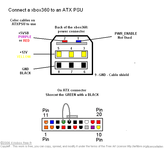
It turns out, six of the pins are used for power transmission and two are used for a "standby" state. This is probably the minimum power required for the sleeping state on the Xbox (I mean how else do you turn it on using the wireless controllers?). Here is the pinout:

Courtesy of that website. Kudos go to them.
If you were to probe the outputs with a multimeter, you will find a 0V potential between the yellow and black UNTIL you supply the PWR_ENABLE pin with +5V. We are going to simply take the +5V USB line (RED) and connect it to the PWR_ENABLE permanently. Then we will connect the yellow and black wires together in parallel because I don't feel like 22ga PVC jacket wire is ever going to safety transmit 150W.

Anyway, I unplugged the charger cord, and immediately sliced into the cable behind the connector. Conveniently enough, the cables are colored accordingly.

8 pins, 8 wires. Life is good.

Strip away more wire and begin soldering things together. Three BLACK in paralle, three YELLOW in parallel, and connect the BLUE and RED/PURPLE.


Your choice on the shrink wrap and external connector. A good choice might be a power strip in case you want to power multiple items with it. Since this power supply is single duty, I soldered in an XT60 connector used for hobby RC.

Sunday, December 9, 2012

GMX Part 2: Combat!

On Friday evening we hadn't left Atlanta until maybe 10 or 11 because SOME PEOPLE were beast-mode machining their robots. Piled into two cars and drove up to Nashville some 4-5 hours later.

The next morning we rolled out of bed to the hotel and set up for the Geek Media Expo's second annual Robot Battled event, or Robot Battles 45 if you'll have it. As we entered, the arena provided by Thomas Kenny was being set up. It was a smaller 4 x 4' arena with a pushout. I was slightly worried about DDT's spin-up time and bouncing but it definitely favored Dominant Mode who operates very well in tight conditions.

Empty for now...
...busy the rest of the day

The Georgia Tech crew brought several robots. We had two antweights between Jim and myself, and six beetleweights created by Gabe Ochoa, Dan Hammer, Xo Wang, Aaron fan, Greg (who wasn't actually there), and myself. 
GT crew and the compound table.

 There ended up being two other antweights, and 2 other beetleweights. Therefore the ants ran double round robin and the beetles ran double elimination. Needless to say, Georgia Tech was over half the competition.

Robots preparing. Everyone looks nice and undamaged right now.

Jim Shealy adds tape to the base of Quantum Platypus to dampen the other spinners.

Dan Hammer working on "The hammer"

Gabe Ochoa, the builder of Mowbot, adding the final preparations.

Mowbot, the champion of the AMMF Robot Battles, sporting a new frame and blade.

Quantum Platypus, the enormous overhead disk spinner.

Gyro King, the massive melty bot made by Aaron Fan and Xo Wang.

My things. Last minute polycarbonate anti-wedge additions being made.

______________________________________________________________________________

DDT vs Quantum Platypus.
DDT pulled the first match of the competition against fellow GT builder Jim Shealy. QP had a nasty overhead hardened A2/plastic composite disk and a wide polycarbonate base for stability and entrapment. Most other robots would have met their doom, but luckily enough DDT's front disk was large and low enough to barely evade the tips of those bars. This is also the first time I have run DDT -_-

DDT proved to have no problem with weapon power. Instant spin up time and enough power to keep it bouncing around the arena. This is not quite compensation for its inability to drive inverted, but it certainly helps. Quantum Platypus's foam adhesives worked well at first, but when DDT struck frame things began to fall apart. DDT wins by JD.

I feel bad for destroying the floor.

Dominant Mode vs Gyro King
Dang! First beetle match of the morning is going to be a big one. Gyro King is a melty brain robot with large 35mm brushless motors for wheels and a solid aluminum frame waterjet from a single billet of 1.5" aluminum. To add to its impressiveness, its motor controllers and bluetooth communications were custom made AND it has hardened s7 teeth. Dominant Mode's drum was rather soft 4130 so I was anticipating the worst. My initial strategy was to box rush, but it doesn't always work out as planned.


Dom takes a nice bite from the tooth support after removing the S7 teeth.
Gyro King was having trouble spinning up. It was designed to spin to over 6000 RPMs but was only getting about 2000. Had it been up to full power it might have been far worse for me considering the number of missed rushes. But Dom removed the S7 teeth by shearing the bolts and nearly ejected Gyro King from the arena. The hit jarred the HDPE dead weights in the robot and high centered its drive wheels. Dom wins by KO.

DDT vs Hardboiled
Return to the antweights to fight last year's winner of GMX Robot Battles. Hardboiled was a fast wedge that didn't show and visible weaknesses. A good driver and reliable drive train was enough for it to clench its first round victory against Green Reaper so I expected him to keep on DDT such that I could not spin up. We would see how well the disk spin up time would be now.


Seems more than sufficient. Even under load, I could torque the disk and spin both robots apart. This bodes very well for DDT seeing as how disk spin up has plagued the old version. DDT wins with an odd flipping slice.

DDT ended up fighting Hardboiled twice more for the round robin format and the championship. All the matches had similar outcomes with equal or greater amounts of bouncing. DDT ends up victorious in both cases. 

Dominant Mode vs Gregbot
Gregbot (or Critical Space Item if you prefer) is a creation of Greg Shikman from Cooper Union. We still have his robot from Dragon Con for whatever reason, and allowed us to run it for GMX. Well, it won its first match against The Hammer and now comes to fight Dominant mode. Gregbot has an overpowered drive train sufficient for 12-pound robots and has an unfathomable translation speed. Gregbot has the potential to really boss Dom around if only it was controllable >_>


Gregbot ended up flipping early from hitting the wall with its springy steel frame. From then on, it was pretty much over. 

Dominant Mode vs Spiky Turtle Screwy Thing
I don't remember the name of this robot exactly, but it was driven by a bright young fellow with a lot of potential. The robot's body was a inverted cake pan and had all sorts of screws sticking out of it as a defense.


I tried my best to not destroy it so I flipped it once and pushed it out. The humane kill for the trutle:)

Dominant Mode vs Mowbot (Finals!)
Finals time! Mowbot suffered some pre-competition damage and was reduced to a pushy bot with a reliable drivetrain. In its last match against Gyro King it suffered a battery short as it was exiting the arena had to be escorted out of the hotel in a fiery bucket. But no harm done, Mowbot was back in action in no time despite looking a bit like it was slapped with baby powder.


Gabe and I both knew that we would lock in a pushy match if we went head on because his front and rear wedges were angled to avoid the drum but contact the frame first. I would try and avoid a head on confrontation like that and instead aim for his corners.

When the match began, he had me where I didn't want to be: pinned against the wall after head-on contact. However when he backed up, I struck the front corner which opened up his front panel and exposed his battery.


After a brief pause we decided to go pushy bots for the rest of the match. The crowd cheered for good sportsmanship and more robot fighting. However the first charge by both robots was the killing blow. Mowbot darted past Dom with its battery hanging out and Dom tagged the trailing battery, pulling it out of its connector. Dom wins in a hilarious final moment. 

Antweight Rumble
At the conclusion of the antweight bracket, we held a small rumble with the three remaining robots in the antweight class.


It turned into a robot dance-off with DDT suggesting its name should be DDR.

Beetleweight Rumble
Two words: Pure. Chaos. Dan and I had agreed to hit weapon to weapon but it seemed like Thomas wanted some action first. By the time Dan and I had any sort of contact, Dom was missing some screws on the side plates. Then, I missed his weapon and fed him my weakened side...


Dominant Mode has never had that much damage before. Both sides incompacitated and a drum bearing shattered. It turns out Dan's robot (The Hammer) pierced through the Ti around the front cap and pulled the entire assembly out. I later gave him those parts as a trophy.

The drum sounded like maracas because of the loose balls inside.

Boom.


Dan Hammer's trophy from me.


Conclusions
Both robots did well but its clear that that Dom needs work. The frame is still vulnerable to horizontal spinners regardless of the angled sides. The inner rails were also tweaked and bent so there needs to be more work in stiffening the front portions of the frame.


The entire competition was pretty rushed for the competitors because of the low number of robots. However, spare batteries and maybe six chargers kept us all going. Given the excitement of the group, I have no doubts we will return to GMX and Robot Battles again!

Big thanks to Xo Wang and Dan Hammer for the excellent video captures! Also thanks to Thomas, GMX, and the MTRAS crew for a great event! On behalf of the Georgia Tech crew, we thank you for a wonderful time!
________________________________________________________________________________

Other awesome moments of the event.
The Hammer vs Gregbot (grudge match)


The Hammer vs Gyro King


Also, the mini highlight reel

Sunday, October 28, 2012

GMX Part 1: Preparation

Those who have seen the beetleweight rumble from the AMMF event will remember that Dominant Mode's drive began failing at the end. With GMX on October 26th, it was time to investigate the source of these issues.

oops

That doesn't look healthy. The cylindrical shaped piece on the table is the front bushing for the KW motor, which had fallen out in all the excitement. It was accompanied by a nice layer of brass pinion dust as it seems to have evaporated in the misalignment. 

I determined that the main faults of this mod were the improper mating of the KW motor to the 280's face plate mount and the inadequate length of shaft used to secure the brass pinion. Because the stock face plate was not intended to mate to these motors, it allowed all sorts of slop in the alignment of the gears. To reach the first cluster gear, the pinion had to be mounted on the tip of the KW motor since the KW motor shaft was sufficiently shorter than the 280's. This meant there was a poor friction connection between the motor and the pinion, and an even worse connection between the pinion and its first cluster gear. No amount of JB Weld could remedy the situation. 

The solution was the remake the motor face plate. This new version would need to have features to properly made the motor concentrically to the gearbox and bring the motor shaft closer to the first cluster gear. I found that a simple flat of 1/8" aluminum was sufficient. 


I made several mistake in the model, but I had the main bolt pattern correct so I was able to match drill the new piece.


The full length of the pinion is now available for contact despite being pressed fully onto the shaft. This was complimented with JB Weld. The internal shafts in the gearbox did stick out the back of the new face plate so the entire end was belt sanded to make that surface flush. For the record, the main two screws that bolt through the gearbox are M2.5 and the pins are 2mm dia. I will make this face plate available as soon as I develop a proper model.


The gearbox and resulting combination. Because I couldn't find the loctite, I opted to JB Weld everything. Hopefully, its insane bonding power will be sufficient for holding screws.

Meanwhile, I have been planning a new antweight in light of Dragon Con Robot Battles. Colson Bot was fun, but not entertaining enough for my tastes. It was time to revive the champion of entertainment: DDT.

This time around, the goals were to increase the rigidity of the frame and ease manufacturing. For me, this basically meant waterjet, waterjet, waterjet.


The main idea was to waterjet two slabs of UHMW and stack them together to compose the main frame. The weight for this upgrade would come from a smaller battery and smaller drive motors. The banebots 24:1 gearmotors were overkill for moving an antweight. Instead I opted for the brass micro gearmotors found at pololu. These would be belted to two dead shafts holding the drive wheels. This drive assembly would be mounted to 1/8" 6061 aluminum plates to keep everything in alignment; I wouldn't trust UHMW to stay rigid enough.


The newest version sunk these plates into the UHMW sides. While the disk remained the same, the weapon was upgraded to a Hacker A20-20L. Similarly, the battery was decreased to 460 mAh, but increased voltage to 11.1 V. This meant approximately 11 kRPMs!


The frame was waterjet with through holes for alignment. First some small nails were inserted to keep it together. Then the side plates could be pressed in and drilled. This assisted in assembly of the rest of the machine. 


Drive module. Those are M1.6 cap screws that go through the front plate of the pololu gearmotors. The dead shaft is 1/4" delrin for the time being.


DDT's frame quickly coming together! Top plates are made from 5XXX anodized aluminum for the purpose of engraving logos later.


The belt system for the drive. The motor side pulley is 1/2" OD for a 3/32" urethane belt. The wheel side has a 5/8" OD and is made of delrin. To simplify the assembly, I am using the bearing properties of delrin instead of opting for bearings or bushings.


When I had first purchased the new lite flite wheels for the robot, I had planned on using larger 2.5" diameter  wheels. Now that I inspect the design, it would must better benefit from smaller wheels. With only 2 days before the competition, I decided to try turning neoprene rubber. I shoved a 1/2" aluminum shaft into the inner diameter of the foam wheels and placed them side by side on my lathe. I spun them at 755 RPM and made .03" passes with a sharp carbide bit. It was messy but returned great results.


The top cover after engraving. Included is the molecule so others can make the connection. DDT the pesticide, killing the antweight robots.


Saturday, October 20, 2012

AMMF: It's Robot Fighting Time!

Robots. One week ago, the second annual Atlanta Mini Maker Faire held its first ever robotic combat event primarily organized by yours truly. It seemed like an opportune time to feature destructive machines given the audience and zany maker atmosphere.

What made this event particularly interesting (other than the fact that I tried to organize it while fighting pneumonia) was the experimental team battle format. An exerpt describing the function of the team rules is described below:
_________________________________________________________________________________

The competition shall be composed of two sets of rounds:
  1. Qualifying Rounds
  2.  Elimination Rounds

Qualifying Rounds
Each match will consist of 4 entrants in a 2v2 format. The alliances per match are random. The winners of the bout are declared when both entrants of the opposing team are incapacitated, unable to display controlled translational movement, or are ejected from the arena. Match length will be 3 minutes. If any number of devices on each team are in the arena and still able to display controlled translational movement, the winner will be decided by a judge’s decision.
At the conclusion of each match, points will be awarded to each robot.
  • 2 points for both the robots on the winning team*
  • 1 point for each robot remaining in the arena

*0 points will be awarded to robots that do not attend their designated match time.*

Robots with byes will be compensated with 2 points.

At a specified time designated by the event organizer, the points for each robot will be tallied and the top 4 devices will advance to the Elimination Rounds.

Elimination Rounds
The winners of each match in the elimination round will be determined using the standard 2011 RFL ruleset.
The remaining 4 robots will engage in single-elimination, 1v1 combat beginning with the semi-final round.
The winners of each semi-finals round will advance to a finals round, where the bracket winner will be determined.

_________________________________________________________________________________

This new format is advantageous because it allows robots to maximize the number of matches they fights in a more condensed time period. However there may be possible conflicts regarding the recharge time typically allotted after each match. This value, of typically 20 minutes, would then drive the frequency of the matches, especially for events with a sparse number of robots. The main negative to this format is the amount of pre-planning required. Walk-up registration is difficult to plan given that most of the match organization is currently done by hand. This would require pre-registration unless an algorithm is used.

For the AMMF, we had 12 robots by the time registration was done; that is, 6 ants and 6 beetles. Michael Jeffries of Near Chaos Robotics assembled the match line up with some quick wit. The idea for the AMMF was to attempt to allow the builders to see the attractions of the faire by hosting matches at preset times during the hour. In the case of this event, every half hour. However, given the low number of robots, it meant that competitors at best case would have a max of 1 or 1.5 hours to look around assuming they don't have robots in both weight classes.

I decided not to enter any of robots directly since I believe the EO should never win their own event.

Cool trophies for the winners of each weight class and rumble.


These were simply laser cut acrylic pieces that were pressed together and then welded using acrylic solvents.

We were placed at the base of the stairs between the CULC and Skiles buildings. It was nice and shady, and the stairs offered free seating for the crowd.


The stands were quickly populated by makers and crowd alike.


I was honestly surprised at the number of attendees. The competition was assembled rather late and not actively publicized yet we had massive waves of viewers throughout the day. Equally impressive were the robots.

The Hammer, one of many robots built at the Invention Studio.

Beetleweights engaged in a qualifiers match.

One team preys on the other team.
The best part of the team format is that no matches were particularly boring. There was always at least one spinner which made from a lot of excitement. Some of the most notable matches at embedded below.


By the end, I decided to have some fun too and threw Dominant Mode in the beetleweight rumble. I'm not supposed to win my own rumble.


More videos can be found at the Near Chaos Robotics Youtube Channel

Mow Bot, the beetleweight champion of the event.
With that, I'll call the event a success. The team format was proven to be a big hit, although I think more has to be done in consideration of the builders. This format is great for the audience but the time between cycles on robots is incredibly small. This left very little time for other builders to see other exhibits. In a normal competition where robot combat is the main event, this might not be as large a problem. Still, it might require back to back matches or lessened recharge time. This implies that the team format is best done with a large number of competitors.

Huge thanks to the competitors and members of the robot community who helped set up. This means Randy, Rob, Mike, and several others who not only helped setup brackets, but unload the arena and bring robots so we can have a good show. You guys made this happen!

'Till next time, BOT ON!