Saturday, July 21, 2012

Clash of the Bots 3: Semi-Domination

A lot of time and project progress passed by. Mostly undocumented because of ME 2110: Creative Decisions and Design.


Nonetheless, Dominant Mode debuted at the COB3 event in North Carolina this past weekend on the 14th. It placed 4th but did not disappoint when it was in optimal shape. Let's recap the final preparations and continue to describe machine performance.

With a completed frame, it was time to push together the weapon. It was composed of four main parts: the drum, the motor can, the stator mount, and the outboard endcap. I had previously intended on having Whyachi machine my drum, but after telling me they couldn't make it or it would cost me $400, I decided to pursue alternate methods.

The drum design then simplified drastically. Instead of the unibody drum, the drum became an assembly of steel bars welded to a grooved tube. There were several competition teams and ME staff that could help me weld so I would save oodles. Plus, I could machine all the parts myself on the mill, lathe, and waterjet. Hardening could be achieved through begging to Braddock Metals in Atlanta, or utilizing a kiln we dug out of a dumpster by the physics building. It was a solid plan.

4130 was selected for the drum body, and 8630 (keyway stock) was selected for the teeth. Both are chromium-molybdenum steels that anneal, harden, and temper at the same temperatures (according to the ASM materials handbook). Plus they were cheap. About $20 for the drum so far.

Some hours of machining later, I had prepped the drums and teeth. Buying 1 ft of material from Online Metals was enough to two drums. No harm in spares right?


The drums were welded together by my friend Craig Wooden. Thanks Craig!

At this point I had put off drum construction that I needed to harden it immediately or run unhardened for the event. This meant I had to use the kiln. Some experimental jiggling of the analog temperature dials found a nice ~1650 deg F of oven temperature. I weaved some magnet wire in between the drum holes for handling since copper melts at higher temperatures than 1600. I placed the drum inside the oven and let it bake for ~2 hours. Then this:


Water bath instead of oil for safety reasons. I think I may have taken too long to transport the piece from the oven to the water. It had a nice oxidation layer that cracked off from expedited rusting.


However, we still observe evidence of hardening via auditory means. A smaller hammer tapped on the side of the hardened drum produced a higher pitch ring than the unhardened one. This is indicative of a tighter packed atomic structure, or a harder material in this case.

The other parts came together as easy as cake. I turned by best piece yet and was able to keep a 1 thou tolerance on all dimensions. The magnet can was simply pressed down inside the can. Lets hope I never need to remove that piece...


... but I did.


This point shows the robot completed and playing with some objects and Michael Jeffries' 30lber Nyx, but little did I know it was nearly a half pound overweight. I took it to the post office to weigh it the week before the event and yeah.

Massive disassembly time and uber machining mode. Each system and component was weighed to determine how much I would need to remove to make weight. Things like motors and electronics could not be changed and were simply held as a minimum weight sum. The drum weighed a whopping 26 oz with motor and all. Because steel was the densest material on the bot, it would receive the machining operation first.

The can was lightened as much as possible by turning away massive aluminum voids. The drum's teeth were castled down to the drum wall. There were some sections of the teeth that had me worried about the penetration of the welds, but this would not be the time to worry about them.

The wheels received a significant amount of attention as well. The wheels, belts, and pulleys weighed about 3.5 oz which is still a butt-ton for the beetleweights. Instead of using bronze sleeve bushings and aluminum hubs, I opted for a single piece Delrin hub. It was light, easily machined, and had semi-lubercative properties which meant I could save on bushing weight. The wheel rubber themselves were recut with some lightening holes along the radius.


Hey check it out! Tweels! I was skeptical about their impact resistance and damping effects on the robot's drive, but it worked well for the time being. Final weight for wheels, belts, and pulleys now sat at ~1.3 oz.

After replacing the metal top and bottom plates with 1/32" polycarb and garolite (so sad!) the robot tips the scale at 48.1 oz. Both mid-plate supports were removed to make weight.

The final shots.


Some nice vinyl logos and a Invention Studio temporary tattoo prepares the bot for screen time. Lets hope vinyl doesn't weigh much. I also prepared some plastic shims as anti-wedge devices. Instead of using the easily-damaged nylon, I opted for .022" thick UHMW. It seemed flexible, but hopefully not too deformable.

July 14th: Competition Day


Michael Jeffries of Near Chaos Robotics was nice enough to drive me up to North Carolina. Clash of the Bots was held at the Scheleiele Museum. A nice indoor, ventilated venue with plenty of space and power was provided. Team pit tables were predetermined and a specific table near the back door was dedicated towards charging lipoly batteries. It was very well organized. I was fortunate enough to be stationed near the arena.


As usual, I didn't take many pictures, but other people did.

Match 1: Ramvac

Without much driving practice going into this match, I was a bit nervous. I've seen this robot time and time before and Sam is without a doubt a good driver. Ramvac itself was a very sturdy wedge. It used 4 of the same modified drive motors I had so it was fast and powerful. It features a UHMW frame with hardened steel on the important parts. I knew I would not be able to go for the knockout, but I would have to use gyro dodges to my advantage to out drive him and score points.


I learned from this match that I should never never never get flipped over at all possible. The weight distribution of the robot made it very front heavy, and inverted driving was abysmal. I think I am fortunate Ramvac decided to revert my robot.

Match 2: Weta

Pete has been competing robots for quite awhile, so I expected a well polished machine. This particular robot is actually available as a kit from his website Kitbots. Conclusion: this must be a good machine. I'm not sure about the particulars on Weta anymore, since Pete mentions he was experimenting with new drive motors and a faster motor. I decide this would be an opportune time to test the max speed of my drum as well.


Let's not do that again. It appears his beater bar is in fact faster and caused me to get flipped. I spend over half the match on my head but am luckily reverted to make an astounding comback in the last 30 or so seconds. If Weta was using his old drive system, I might have been in trouble.


He dented my Ti armor :(

Inverted driving is a capital item to be addressed before Dragon Con! At least we see how effective the angled plating is in deflecting blows.

Intermission: Robot Panic

When I placed Dom into the box to face Shame Spiral, I noticed that only one drive side was responsive. The other ESC emitting the "no signal" or "out of center" error. I am forced to use my postponement to discover the error. All wires a nice and glued in (what a pain) with no connections lose. I decide to remove DDT's receiver and run the bot off two receivers, assuming the ch2 on my Spektrum Ultralite had failed. However, I eventually discovered my ch 2 on my repaired dx6i had died. Julie from Near Chaos Robotics lent me her tx for the remainder of the competition. Thanks Julie!

Match 3: Shame Spiral

A tough wedge of shock-mounted UHMW and hardened steel outer surfaces (actually harder than my expected drum hardness). I had fought Shame Spiral before at Dragon Con and was easily defeated by Thomas' driving skill and well designed deflective wedge. I hoped this time that my increased speed and anti-wedge devices would allow one good hit to invert him, where I would then leave him for the remainder of the match. I received none such luck.


Despite hits to his sides, none were able to grab and toss. As a result, I was never able to get him off the ground. Through all the abuse, my power plug (a deans micro) falls out and I tap.

Match 4: Ramvac

I was more confident this time, knowing that I had won a match against him before. However the Tx business set back the beetle brackets pretty far and I had minimal time to charge. I would have to take it easy this time and line up good shots on his sides or back.


Match 5: Grande Tambor

The expedited beetle bracket takes it toll. I had only 10 mins to charge this time, but I decided some match was better than none. This would be the ultimate test of my armor as Grande is a hard hitter and I expected a few outages during the match from undervoltage.


Every time Dom pauses is a drive esc reset. There wasn't really much I could do except wait to reconnect. I confess I believe it is a terrible way to be eliminated, but the angled armor held up well and given all issues are resolved Dom will be back for a rematch!

Well, after I fix this:


Post-competition analysis:

Clash of the Bots 3 was a tough competition with a lot of great robots. Dominant mode went 3-2, which is actually the worst record I have ever had for a new robot. No longer can I depend on the knockout win, I actually have to start buying spare batteries. I also need to investigate the control losses during the match. Its possible the battery is the issue, as in the current draw from my motors, but it could also be a need for more bus capacitance. I will have to revisit my electronics to determine the cause of these mysterious power outages.

Conclusion, Dominant Mode is a keeper! It would be nice if I could reallocate more weight to the rear of the robot such that inverted driving was more effective. I also need to make sure the pinions never disconnect from the KW motors. I will be contemplating fixes for the drum's bearing setup, but I think that hit from Grande was an exception, since I was not spinning. I will however be buying more batteries in reflection of the short charge times.

Thanks to Robert of Mad Overlord, we also have high-speed camera footage to download for a limited time only!

I also want to thanks Mike Gellatly of Busted Nuts Robotics for helping to machine some semi-complex aluminum angle blocks for Dom's side armor.

Monday, May 28, 2012

Let's Play a Game...

... I'll show you some pictures, and you try to figure out what it is. Ready? GO!


In the meantime, let me tell you about support material on the Ultimaker.

IT IS AMAZING! While it is no Dimension or Objet, it still has settings for breakaway support material. That is, vertical planes of the smallest thickness the 3D printer can muster.

It builds up these support layers along with the main model up until the overhanging layer is met. Then it simply prints on top of the slats. Some x-acto kniving is required but the result is well worth it.

Anyway, the mystery model is...


That girl! (Hana) She is from some anime I havent heard of, yet she was uploaded onto Thingiverse. I search for anime occasionally in hopes that Miku might pop up.


All I had to do post operation was snap off the supporting material. Comes off very easily because of the minimal contact points.


And check this out, her hair is NOT attached to her back. That is to mean they are separate pieces. Her neck is the only attachment point between the head and shoulders. Support material woot!

Super Awesome Super Post

THIS POST HAS EVERYTHING!

Because of:
  1. finals
  2. senior design expo
  3. self-motivation and underestimation of time
A ton of progress on several projects (new and old) went without documentation. SO LET US DOCUMENT.

Razor Wind v1.4: Pneumatic Wheelpod Edition
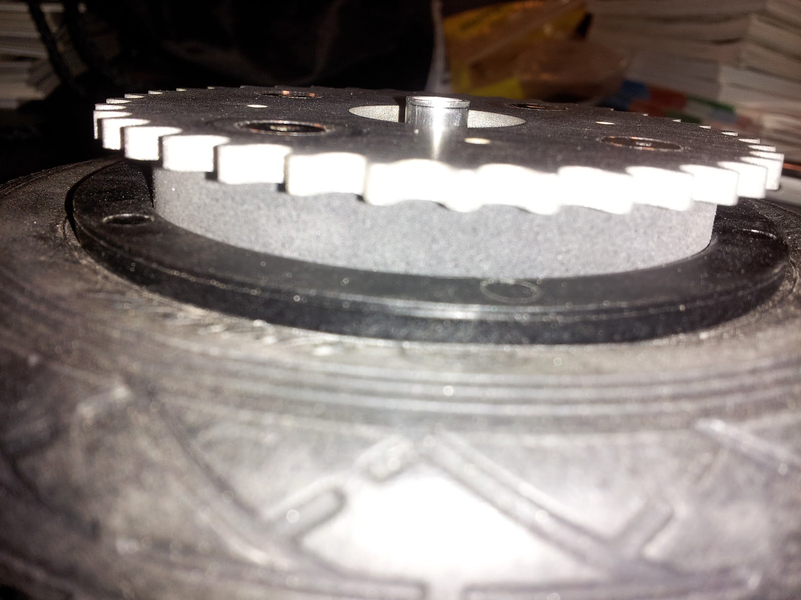
Colson wear on my scooters end up looking like this after about a month.


That is, uneven wear, and reduced diameter. Those are supposed to be 4" OD wheels, but I recall measuring maybe 3.5 on the smaller side. This results in not only poor performance on the vehicle, but a danger when turning. The residual lip on the right side results in some drifts on lower angle leans.

I decided pneumatic wheels were worth looking into. Given the hub isn't damaged, I would replace the outer tire pretty easily instead of machining a new wheel every time. I typically strayed from pneumatic wheels because the valve stem was annoying to deal with and I couldn't find any smaller than 6". Until now...


I found these guys as popular wheel choices for mountain rollerblading. Aero 125s v2. (Nordic Skiing?) A bit pricey at $47 a wheel, but I don't expect to be damaging the hubs. At most, I would purchase new tires or inner tubes, which beats out paying $20-30 for new pneumatic casters in the long run.


They actually measure 5" OD!


...and 1" wide approximately. Although they were still 1" OD greater than my current set, the modifications to the frame were easy to make because adapter fork and wheelpod.


The mating block was simplified to a rectangular bar with the same hole patterns. The fork plates were extended to accommodate the 5" OD wheel.


The rear wheel required more work. I waterjet cut a circle from 1/2" UHMW to act as a large spacer. This matched against the inner regions of the wheel hub and the bearing tube for a solid concentric mate. All of it bolted together using the wheel's original bolt holes.


Pneumatic wheel Scooter Buddies! (Scooty Puff, Aaron Fan)

Verdict: Pneumatic wheels are awesome! Increased rolling friction from wheel depression, but overall a better riding experience. Bumps and road imperfections are negligible for the most part. Cost and maintainability are to be seen.

Kawaiicopter v1.0
Its no secret I have an affinity for ground vehicles. I often tell my research associates, "Air and water are were your things DIE". So why am I bothering with an areal vehicle? Well the past spring semester, I partook in two systems classes, one of which was taught by the magnificent Magnus Egerstedt who inspired me to embark on more ambitious projects. So in light of this challenge, I elected to build something that used control theory, which just happened to be a good excuse to learn PCB layout, which ended up becoming a trirotor project using brushed EDFs. OH GOD.

There are a few reasons why people choose quad rotors versus n rotors.

  1. modulation of the rotor output works out nicely in Cartesian coordinates
  2. you can have matched sets of clockwise and counter clockwise rotating blades to counteract rotor torque on the body.
I was well aware of item 2 before embarking on the project. For kicks, I wanted to see how terrible of yaw rotations I would be dealing with. 


It rotates. *sigh*. Looks like we are on to phase 2.

If you can't have counter rotating props, another alternative are vectored thrust. That is, point the fans in a direction to counter act the rotor torque.

A few hours of modeling resulted in this, a rather hefty cam-driven servo mechanism. I bought three of the cheapest servos I could find on Hobbyking for the vectoring duty. Even if they were weak, it didn't matter. The servos cams were far enough from the point of rotation for maximum mechanical advantage.


A flat on the end of a servo shaft mates nicely with a 3D printer boo boo which left a D profile on the interior. 


A section of the main body, which holds the life shaft. that is a long 4-40 screw with an o-ring sandwiched between two brass washers. The o-ring was intended to act as a low-compression spring to ensure minimal axial play yet more tolerable surface friction between the moving components. The EDF mount would be threaded onto the end.


Servo cam in place...


...and the completed test frame! I'll do use a favor and fast forward a few minutes...


Verdict: it produces an enough thrust to force a rotation! Unfortunately, I maxed out the power supply running three EDFs simultaneously, so we will have to wait for the PCB to see if it can fly. (I still believe in my calculations!)

Speaking of which...


My first PCB! I rushed the design out in about 2 days, which is not too bad. Thanks to Aaron, Xo, and SparkFun for the occasional tutorial or piece of advice. There was a lot of wasted space on the board, but for a flat board rate and first manual traces I though I would keep it simple. Still, it turns out there were a few mistakes. Can you spot them?


Here is one. Arduino lovers avert your eyes! Oh poor pins...
The other mistake lay in the trace connections. While I'm not sure what happened with my gate drivers, my motor terminals should have been connected to V+ and the MOSFET drain. Instead, I connected GND and drain, which meant the arduino was pulsing a connection from GND to GND. :(

At least the receiver communications worked. This concludes the failed v1.0 Time to move onto the next revision.


Kawaiicopter v1.2 (What happened to v1.1?)
Slightly discouraged, I decided to calm my ambitions. By this time, finals were over and I could no longer present anything for Robot Friday. So lets build a traditional quadrotor with a lighter frame and actually spend some time double checking the circuit this time.


The Invention Studio decided to purchase an Ultimaker, so I decided that and a combination of carbon rods would be a durable and light frame.


A fine representation of the construction. That is green PLA, printed shortly after the pink panther woman shown above.


Tiny little aluminum hubs attach to the motor shafts. 1.5mm bore.


The open end is tapped for 4-40, where an o-ring and flat head screw meets it. This is my version of a prop saver. Enough friction to get it moving, but the ability to slip in the worst scenarios.


Wires feed into the frame here...


... and exit into the main body. Much cleaner than most quadrotor builds.


Cuuuuuute. By recommendation of Charles, I decided to skip the gate driver transistors and run the MOSFET directly from the arduino outputs. This short flight test is testimony to its success.

With that said, the new board:


This guy is being made by DorkbotPDX, and should arrive in about 10 days. Only $20 for three copies! Give them a try.


Current weight with battery is 130.4 grams! So far so good.

Tired. Build On!

Wednesday, March 7, 2012

Return of the Roboteer

After exploding over $160 in brushless ESCs, I've decided to take a break from electric vehicles for the time being and get back to the finer points of combat robotics. Last year I had begun the development of a nifty angle-armor design with an eggbeater for a weapon. I tried to utilize the full capabilities of the Invention Studio, but I realize now I was missing the mark in design. So with that said, a few modifications:


In light of my new fondness for systems controls, this new version will be called "Dominant Mode".

New design features include:

  • Center support wall now used tabs instead of slots. # of screws reduced from two to one. This change added alignment benefits and more supporting material. The original design used only slots which meant the vertical misalignment was possible if the end-drilled holes were not exact. Using only one screw leaves more 2024 Al frame rail.
  • No more b16 gearmotors! While I am still using the indirect drive method (dual belts), I dropped the custom B16 gearboxes because the tolerances were too tight. Instead, I created a frankenbox from B16 motors (reasonable KV but high KT) with the "Ebay motors" gearboxes (10:1 ratio). With 15k rpms at 12v on a 10:1 gearbox, I should be getting 1850 rpms at each wheel at 14.8v. That is  FAST!
  • New drum design. That right, I said drum. Even with the 8+ hours of machining that block of A2 for the eggbeater, I just cant ignore the benefits of the drum. More difficult to make, but stronger overall, higher MOI, and more geometrically effective against vertical disks. It also allows me to experiment with my new drum design, detailed below.
  • No more Scorpion HX. Unfortunately not everything can become a positive. Due to bad dimension spec's by turnigy, I no longer have space in the robot for my scorpion HX. My alternatives are using the BB3-9 ESCs or the HMC 3-9 ESCs. While essentially the same, one doesnt suffer from transient neutral zone drift...
So once again I began building without documenting my steps (building gets too exciting to grab a camera, ugg).


Began by machining my wheels. That is .75" dia case hardened Al shaft wit ha groove for my urethane belts and a 3/8" bore for my bushings. A 1/4" dowel pin will press into my main frame rails and act as shafting for these guys. Like so:


Pretty sweet eh? I might be able to drive it soon! The urethane belts were custom made using cord stock from mcmaster-carr. Just hold the ends over an open flame and push them together. Removing from flame, the urethane will cool and fuse together. Then clip off the excess.


The actual tread come from a 3/8" sheet of 60A durometer SBR rubber. WATERJET GO!

A nice little feature to mention about the new frame rails are the tabs for the top and bottom plate. Additional rigidity and no quirky misalignment. Perfect every time! Here are the top and bottom plates:


The black plate is the top made from anodized 5052 Al and the bottom plate is 7075 Al (nothing but the good stuff!). Both are approximately 1/32" thick. I am really looking forward to engraving on the top. I'll pick some rather aggressive exponential to drive the "Dominant Mode" point.


On the bot

Over the weekend, I took the liberty of wiring up the robot. Knowing how little space I had remaining, I ended up with the electronics cube.


The bus caps on the weapon esc actually had to be resoldered to the board in a strange parallel combination. I had a chance to try my p0w3r bus idea again with the escs. The entire assembly is stuff! 10 points to the person who can find my receiver.


In the bot. I later surrounded all the surfaces with foam padding. ESD of course.

So some of you may be wondering, what will happen to that champion bot Cake? Well since I didn't end up using my B16's, scorpion HX, orange RXs, or my TP 3s 800mAH lipoly, I could very well reassemble! But with a special modification...


Muahahaha...

Next time, videos of driving and drum components build!