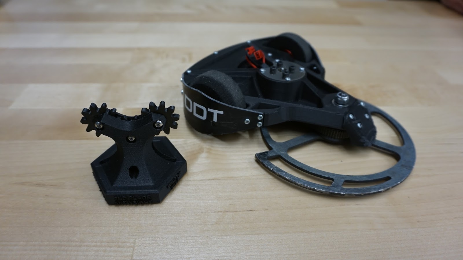
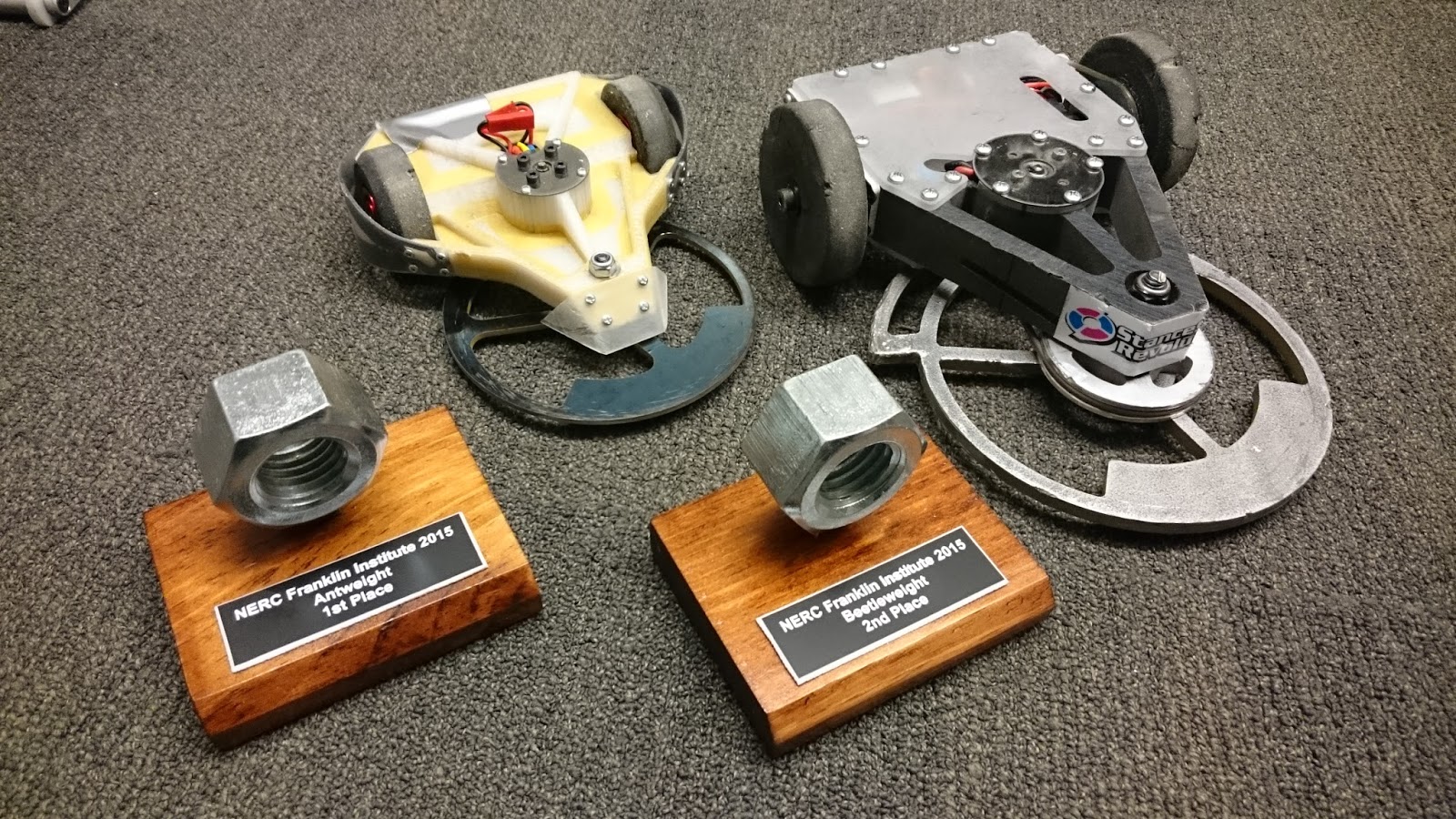
... I'll show you some pictures, and you try to figure out what it is. Ready? GO!
In the meantime, let me tell you about support material on the Ultimaker.
IT IS AMAZING! While it is no Dimension or Objet, it still has settings for breakaway support material. That is, vertical planes of the smallest thickness the 3D printer can muster.
It builds up these support layers along with the main model up until the overhanging layer is met. Then it simply prints on top of the slats. Some x-acto kniving is required but the result is well worth it.
Anyway, the mystery model is...
That girl! (Hana) She is from some anime I havent heard of, yet she was uploaded onto Thingiverse. I search for anime occasionally in hopes that Miku might pop up.
All I had to do post operation was snap off the supporting material. Comes off very easily because of the minimal contact points.
And check this out, her hair is NOT attached to her back. That is to mean they are separate pieces. Her neck is the only attachment point between the head and shoulders. Support material woot!
+C : The Variable Constant
Modeling life's dichotomies one integration at a time.
Monday, May 28, 2012
Super Awesome Super Post
THIS POST HAS EVERYTHING!
Because of:
I found these guys as popular wheel choices for mountain rollerblading. Aero 125s v2. (Nordic Skiing?) A bit pricey at $47 a wheel, but I don't expect to be damaging the hubs. At most, I would purchase new tires or inner tubes, which beats out paying $20-30 for new pneumatic casters in the long run.
They actually measure 5" OD!
...and 1" wide approximately. Although they were still 1" OD greater than my current set, the modifications to the frame were easy to make because adapter fork and wheelpod.
The mating block was simplified to a rectangular bar with the same hole patterns. The fork plates were extended to accommodate the 5" OD wheel.
The rear wheel required more work. I waterjet cut a circle from 1/2" UHMW to act as a large spacer. This matched against the inner regions of the wheel hub and the bearing tube for a solid concentric mate. All of it bolted together using the wheel's original bolt holes.
Pneumatic wheel Scooter Buddies! (Scooty Puff, Aaron Fan)
Verdict: Pneumatic wheels are awesome! Increased rolling friction from wheel depression, but overall a better riding experience. Bumps and road imperfections are negligible for the most part. Cost and maintainability are to be seen.
Because of:
- finals
- senior design expo
- self-motivation and underestimation of time
A ton of progress on several projects (new and old) went without documentation. SO LET US DOCUMENT.
Razor Wind v1.4: Pneumatic Wheelpod Edition
Colson wear on my scooters end up looking like this after about a month.
That is, uneven wear, and reduced diameter. Those are supposed to be 4" OD wheels, but I recall measuring maybe 3.5 on the smaller side. This results in not only poor performance on the vehicle, but a danger when turning. The residual lip on the right side results in some drifts on lower angle leans.
I decided pneumatic wheels were worth looking into. Given the hub isn't damaged, I would replace the outer tire pretty easily instead of machining a new wheel every time. I typically strayed from pneumatic wheels because the valve stem was annoying to deal with and I couldn't find any smaller than 6". Until now...
I found these guys as popular wheel choices for mountain rollerblading. Aero 125s v2. (Nordic Skiing?) A bit pricey at $47 a wheel, but I don't expect to be damaging the hubs. At most, I would purchase new tires or inner tubes, which beats out paying $20-30 for new pneumatic casters in the long run.
They actually measure 5" OD!
...and 1" wide approximately. Although they were still 1" OD greater than my current set, the modifications to the frame were easy to make because adapter fork and wheelpod.
The mating block was simplified to a rectangular bar with the same hole patterns. The fork plates were extended to accommodate the 5" OD wheel.
The rear wheel required more work. I waterjet cut a circle from 1/2" UHMW to act as a large spacer. This matched against the inner regions of the wheel hub and the bearing tube for a solid concentric mate. All of it bolted together using the wheel's original bolt holes.
Pneumatic wheel Scooter Buddies! (Scooty Puff, Aaron Fan)
Kawaiicopter v1.0
Its no secret I have an affinity for ground vehicles. I often tell my research associates, "Air and water are were your things DIE". So why am I bothering with an areal vehicle? Well the past spring semester, I partook in two systems classes, one of which was taught by the magnificent Magnus Egerstedt who inspired me to embark on more ambitious projects. So in light of this challenge, I elected to build something that used control theory, which just happened to be a good excuse to learn PCB layout, which ended up becoming a trirotor project using brushed EDFs. OH GOD.
There are a few reasons why people choose quad rotors versus n rotors.
Kawaiicopter v1.2 (What happened to v1.1?)
Slightly discouraged, I decided to calm my ambitions. By this time, finals were over and I could no longer present anything for Robot Friday. So lets build a traditional quadrotor with a lighter frame and actually spend some time double checking the circuit this time.
The Invention Studio decided to purchase an Ultimaker, so I decided that and a combination of carbon rods would be a durable and light frame.
A fine representation of the construction. That is green PLA, printed shortly after the pink panther woman shown above.
Tiny little aluminum hubs attach to the motor shafts. 1.5mm bore.
The open end is tapped for 4-40, where an o-ring and flat head screw meets it. This is my version of a prop saver. Enough friction to get it moving, but the ability to slip in the worst scenarios.
Wires feed into the frame here...
... and exit into the main body. Much cleaner than most quadrotor builds.
Cuuuuuute. By recommendation of Charles, I decided to skip the gate driver transistors and run the MOSFET directly from the arduino outputs. This short flight test is testimony to its success.
With that said, the new board:
This guy is being made by DorkbotPDX, and should arrive in about 10 days. Only $20 for three copies! Give them a try.
Current weight with battery is 130.4 grams! So far so good.
Tired. Build On!
Its no secret I have an affinity for ground vehicles. I often tell my research associates, "Air and water are were your things DIE". So why am I bothering with an areal vehicle? Well the past spring semester, I partook in two systems classes, one of which was taught by the magnificent Magnus Egerstedt who inspired me to embark on more ambitious projects. So in light of this challenge, I elected to build something that used control theory, which just happened to be a good excuse to learn PCB layout, which ended up becoming a trirotor project using brushed EDFs. OH GOD.
There are a few reasons why people choose quad rotors versus n rotors.
- modulation of the rotor output works out nicely in Cartesian coordinates
- you can have matched sets of clockwise and counter clockwise rotating blades to counteract rotor torque on the body.
I was well aware of item 2 before embarking on the project. For kicks, I wanted to see how terrible of yaw rotations I would be dealing with.
It rotates. *sigh*. Looks like we are on to phase 2.
If you can't have counter rotating props, another alternative are vectored thrust. That is, point the fans in a direction to counter act the rotor torque.
A few hours of modeling resulted in this, a rather hefty cam-driven servo mechanism. I bought three of the cheapest servos I could find on Hobbyking for the vectoring duty. Even if they were weak, it didn't matter. The servos cams were far enough from the point of rotation for maximum mechanical advantage.
A flat on the end of a servo shaft mates nicely with a 3D printer boo boo which left a D profile on the interior.
A section of the main body, which holds the life shaft. that is a long 4-40 screw with an o-ring sandwiched between two brass washers. The o-ring was intended to act as a low-compression spring to ensure minimal axial play yet more tolerable surface friction between the moving components. The EDF mount would be threaded onto the end.
Servo cam in place...
...and the completed test frame! I'll do use a favor and fast forward a few minutes...
Verdict: it produces an enough thrust to force a rotation! Unfortunately, I maxed out the power supply running three EDFs simultaneously, so we will have to wait for the PCB to see if it can fly. (I still believe in my calculations!)
Speaking of which...
My first PCB! I rushed the design out in about 2 days, which is not too bad. Thanks to Aaron, Xo, and SparkFun for the occasional tutorial or piece of advice. There was a lot of wasted space on the board, but for a flat board rate and first manual traces I though I would keep it simple. Still, it turns out there were a few mistakes. Can you spot them?
Here is one. Arduino lovers avert your eyes! Oh poor pins...
The other mistake lay in the trace connections. While I'm not sure what happened with my gate drivers, my motor terminals should have been connected to V+ and the MOSFET drain. Instead, I connected GND and drain, which meant the arduino was pulsing a connection from GND to GND. :(
At least the receiver communications worked. This concludes the failed v1.0 Time to move onto the next revision.
Kawaiicopter v1.2 (What happened to v1.1?)
Slightly discouraged, I decided to calm my ambitions. By this time, finals were over and I could no longer present anything for Robot Friday. So lets build a traditional quadrotor with a lighter frame and actually spend some time double checking the circuit this time.
The Invention Studio decided to purchase an Ultimaker, so I decided that and a combination of carbon rods would be a durable and light frame.
A fine representation of the construction. That is green PLA, printed shortly after the pink panther woman shown above.
Tiny little aluminum hubs attach to the motor shafts. 1.5mm bore.
The open end is tapped for 4-40, where an o-ring and flat head screw meets it. This is my version of a prop saver. Enough friction to get it moving, but the ability to slip in the worst scenarios.
Wires feed into the frame here...
... and exit into the main body. Much cleaner than most quadrotor builds.
Cuuuuuute. By recommendation of Charles, I decided to skip the gate driver transistors and run the MOSFET directly from the arduino outputs. This short flight test is testimony to its success.
With that said, the new board:
This guy is being made by DorkbotPDX, and should arrive in about 10 days. Only $20 for three copies! Give them a try.
Current weight with battery is 130.4 grams! So far so good.
Tired. Build On!
Wednesday, March 7, 2012
Return of the Roboteer
After exploding over $160 in brushless ESCs, I've decided to take a break from electric vehicles for the time being and get back to the finer points of combat robotics. Last year I had begun the development of a nifty angle-armor design with an eggbeater for a weapon. I tried to utilize the full capabilities of the Invention Studio, but I realize now I was missing the mark in design. So with that said, a few modifications:
In light of my new fondness for systems controls, this new version will be called "Dominant Mode".
New design features include:
In light of my new fondness for systems controls, this new version will be called "Dominant Mode".
New design features include:
- Center support wall now used tabs instead of slots. # of screws reduced from two to one. This change added alignment benefits and more supporting material. The original design used only slots which meant the vertical misalignment was possible if the end-drilled holes were not exact. Using only one screw leaves more 2024 Al frame rail.
- No more b16 gearmotors! While I am still using the indirect drive method (dual belts), I dropped the custom B16 gearboxes because the tolerances were too tight. Instead, I created a frankenbox from B16 motors (reasonable KV but high KT) with the "Ebay motors" gearboxes (10:1 ratio). With 15k rpms at 12v on a 10:1 gearbox, I should be getting 1850 rpms at each wheel at 14.8v. That is FAST!
- New drum design. That right, I said drum. Even with the 8+ hours of machining that block of A2 for the eggbeater, I just cant ignore the benefits of the drum. More difficult to make, but stronger overall, higher MOI, and more geometrically effective against vertical disks. It also allows me to experiment with my new drum design, detailed below.
- No more Scorpion HX. Unfortunately not everything can become a positive. Due to bad dimension spec's by turnigy, I no longer have space in the robot for my scorpion HX. My alternatives are using the BB3-9 ESCs or the HMC 3-9 ESCs. While essentially the same, one doesnt suffer from transient neutral zone drift...
So once again I began building without documenting my steps (building gets too exciting to grab a camera, ugg).
Began by machining my wheels. That is .75" dia case hardened Al shaft wit ha groove for my urethane belts and a 3/8" bore for my bushings. A 1/4" dowel pin will press into my main frame rails and act as shafting for these guys. Like so:
Pretty sweet eh? I might be able to drive it soon! The urethane belts were custom made using cord stock from mcmaster-carr. Just hold the ends over an open flame and push them together. Removing from flame, the urethane will cool and fuse together. Then clip off the excess.
The actual tread come from a 3/8" sheet of 60A durometer SBR rubber. WATERJET GO!
A nice little feature to mention about the new frame rails are the tabs for the top and bottom plate. Additional rigidity and no quirky misalignment. Perfect every time! Here are the top and bottom plates:
The black plate is the top made from anodized 5052 Al and the bottom plate is 7075 Al (nothing but the good stuff!). Both are approximately 1/32" thick. I am really looking forward to engraving on the top. I'll pick some rather aggressive exponential to drive the "Dominant Mode" point.
On the bot
Over the weekend, I took the liberty of wiring up the robot. Knowing how little space I had remaining, I ended up with the electronics cube.
The bus caps on the weapon esc actually had to be resoldered to the board in a strange parallel combination. I had a chance to try my p0w3r bus idea again with the escs. The entire assembly is stuff! 10 points to the person who can find my receiver.
In the bot. I later surrounded all the surfaces with foam padding. ESD of course.
So some of you may be wondering, what will happen to that champion bot Cake? Well since I didn't end up using my B16's, scorpion HX, orange RXs, or my TP 3s 800mAH lipoly, I could very well reassemble! But with a special modification...
Muahahaha...
Next time, videos of driving and drum components build!
Thursday, March 1, 2012
Razor Wind v1.3: There I Fixed It
It took about 10 minutes to fix the damage brought from Friday's disaster. I decided the best (aka most economical) solution was to scrounge for some countersink 1/4-20 screws and use some low profile nuts or locknuts to secure the angle bracket to the base. The main difference here is that the bracket is secured from the bottom instead of tapping into the soft aluminum from the top. WE HAVE REAL STEEL THREADS!
I realized how my locknuts wouldnt give clearance to the folding joint parts. Luckily I found some 8020 hardware to abuse.
Don't tell anyone how much money I just wasted, but it worked hella well.
While I was at it, I looked to repair the damaged throttle also from last week's fall. The thumb stick had broken off, and the soft plastic parts had deformed enough to impede the movement of the throttle ring.
To replace the thumb stick, I drilled a hole into the remaining surface, tapped it for 4-40, filled the hole with loctite, threaded a 4-40 standoff in its place, and finally immersed the entire thing in goop.
Oh yeah, that's beautiful.
I tried to cut away the obstructing material with my handy dandy knives but to no avail. Without lubercant in sight, I decided to waste some of that (damned) silicon thermal compound in the joint.
Surprisingly, it worked really well!
Friday, February 3, 2012
Razor Wind: Waterproof Scooter is not Waterproof (and other modes of failure)
6pm Wednesday I was in Van Leer wanting to return home and it was raining outside. Last post I had made my attempts to partially waterproof the scooter and was looking forward to a way to test them out. Rather than carefully submerging the body into a controlled volume of water, Aaron and I said screw it and jumped into the massive flooding that is Atlanta.
The verdict is that the scooter is water resistant but in the wrong way. The top is somehow water permeable yet the bottom retains it very well. Something to be said about the sealing job I did.
I actually had to pour my scooter over a sink to rid of the water. I suppose the takeaway from this is that if I want water resistance, I cannot have accessibility to the internals.
That night I lost ANOTHER HK cartroller and an arduino nano. This project is eating up electronics lately.
Now today, I was beasting it to my Heat Transfer class, traveling no less than 15 mph, when I curb jumped and splattered on the concrete.
Turns out that jump was the last straw on the threads holding the steering column to the base chassis and all of them fell to sheer. I expect the quickest fixes will be the rebuild the plate from steel (instead of Aluminum) or to use a countersink screw and locknut combination (both of which I have).
I'm going to sleep.
Monday, January 30, 2012
Razor Wind: I Hate Rain Edition (Upgrades!)
It is a well known fact that Saftey Razor may have been better than Razor Wind for one particular reason. Safety Razor's electronics were bundled and epoxy potted on the end of the motor, making for a very weatherproof and indestructible setup. While Razor Wind had better performance characteristics, it did not have nearly the same luck.
Last week Monday, we had some rather harsh thunderstorms roll over campus and I decided to ride the scooter in the wet. Story short, I noticed a little puff of smoke that was formerly the servo tester. I almost wished it was the esc, because unlike the servo tester, I have multiples of the HK escs.
Downtime means upgrade time, so let us look down the list of things I've wanted to do but never felt like opening a working device to implement.
Speaking of indicators, Turnigy engineers impress me with the concept of a 'solder fuse', which tripped internally in my 6s 5000mAh lipoly pack when the esc blew. Probably saved me another 70 dollars right there.
This result was frustrating but not deterring. Using my last remaining spare, I decided to go forward with a variation of the mod. This time, we should use the heat transfer traces. This was nice because I only had the invert the capacitors.
Instead of solder paste, I pulled one of the heat transfer pads off the undersides of the heatsinks and tossed it between the aluminum heat spreader and the traces. This version is working flawlessly.
OKAY, so mod #1 completed. Now we can hit up weatherproofing efforts.
I figured most of the moisture was entering though the ventilation zone on the rear end but it couldnt hurt to seal up all the cracks. While performing the esc mod, I grabbed some RTV Silicon gasket maker and filled in the corners like caulking.
The opening over the esc was covered using a panel of 1/32" 7075 Al. I took the opportunity to make a water right exit for the esc plugs, which not only looks cool but also stabilizes the connection.
Note the blue edge around the top cover. The RTV Silicon seeped from the edges there a bit.
Fangoriously bright LEDs to indicate power through the scooter.
I hope I never have to test the functionality of my sealing job... Item #2 complete.
From my experiences letting other people try riding my scooter, it was clear that control was not its strong point. I attribute this to the rather shoddy rapid prototyped throttle I made last semester and the servo tester used to convert A to D.
So the throttle crazy began. I purchased maybe three different types of throttles (with spares. Say, does anyone need a throttle?) to select one thumb throttle from an ebay vendor selling 'American Chariots'.
Should you decide to purchase one, I'll save you the setup finagling and tell you the RED wire is +5V, the GREEN wire is output, and the YELLOW wire is ground. Not intuitive at all and I suppose I should be fortunate I didnt destory the thing.
I paired this new throttle up with an Arduino Nano (knockoff) to replace the servo tester. Not only was this guy smaller, but with some slick coding from Shane Colton I was granted control variables to handle throttle limiting and ramping rates. Exciting!
You can follow that right? Shane's Code can be found at the bottom of this Instructables page.
Items 3 and 4 completed! Finally, nothing makes things look awesomer than a bunch of reflective stickers.
Arduino Pride!
Last week Monday, we had some rather harsh thunderstorms roll over campus and I decided to ride the scooter in the wet. Story short, I noticed a little puff of smoke that was formerly the servo tester. I almost wished it was the esc, because unlike the servo tester, I have multiples of the HK escs.
Downtime means upgrade time, so let us look down the list of things I've wanted to do but never felt like opening a working device to implement.
- Weatherproofing
- New Throttle
- Controlled Response from Throttle
- Fanless esc (no random protrusion from the top)
- Make it look pretty
Over the week, I've had the chance to tackle ALL OF THEM.
First, the esc needed a low profile modification in order to seal the upper deck. Simply removing the fan would have done the trick but without convective cooling I was worried about esc overtemp. So I went one step further and increased the size of my heatsink... THE ENTIRE CHASSIS.
Here we see the heatsink off the boards cooling WTF?! Traces?!
Even though the SO-8 package MOSFETs are designed to cool through the PCB, I wasn't convinced it was the best way to dissipate heat. The other side of the board had the ass-ton of FETs required to run, *shudder*, 150A.
So the obvious solution in my mind (at the time) was to resolder the components such that the FETs were exposed. So here we go desoldering all the headers and caps.
After an hour of desoldering, time to resolder.
The Aluminum of course would then be mounted against the base plate and the entire thing would be clamped down with some extra 2-56 cap screws. It is awesomely tiny compared to the stock product!
It looked pretty shnazzy after completion. Some thermal compound would be added between the FETs and the aluminum heat spreader shown below.
The Aluminum of course would then be mounted against the base plate and the entire thing would be clamped down with some extra 2-56 cap screws. It is awesomely tiny compared to the stock product!
Testing indicated that everything worked as planned, but horror struck with I added the SILICON thermal paste to the FETs. I powered it up and I instantly lost three FETs on the startup tones.
The faults indicate that there was a short, which perplexes me because I had it running the night before. The only thing different between the two setups was the addition of NON-CONDUCTIVE thermal paste. Needless to say I'll be doing this differently next time. (un)Fortunately, Digikey has the NTMFS4833N power MOSFET for min purchase of 5000. Anybody else want to split a pack?Speaking of indicators, Turnigy engineers impress me with the concept of a 'solder fuse', which tripped internally in my 6s 5000mAh lipoly pack when the esc blew. Probably saved me another 70 dollars right there.
This result was frustrating but not deterring. Using my last remaining spare, I decided to go forward with a variation of the mod. This time, we should use the heat transfer traces. This was nice because I only had the invert the capacitors.
Instead of solder paste, I pulled one of the heat transfer pads off the undersides of the heatsinks and tossed it between the aluminum heat spreader and the traces. This version is working flawlessly.
OKAY, so mod #1 completed. Now we can hit up weatherproofing efforts.
I figured most of the moisture was entering though the ventilation zone on the rear end but it couldnt hurt to seal up all the cracks. While performing the esc mod, I grabbed some RTV Silicon gasket maker and filled in the corners like caulking.
The opening over the esc was covered using a panel of 1/32" 7075 Al. I took the opportunity to make a water right exit for the esc plugs, which not only looks cool but also stabilizes the connection.
Note the blue edge around the top cover. The RTV Silicon seeped from the edges there a bit.
Fangoriously bright LEDs to indicate power through the scooter.
I hope I never have to test the functionality of my sealing job... Item #2 complete.
From my experiences letting other people try riding my scooter, it was clear that control was not its strong point. I attribute this to the rather shoddy rapid prototyped throttle I made last semester and the servo tester used to convert A to D.
So the throttle crazy began. I purchased maybe three different types of throttles (with spares. Say, does anyone need a throttle?) to select one thumb throttle from an ebay vendor selling 'American Chariots'.
Should you decide to purchase one, I'll save you the setup finagling and tell you the RED wire is +5V, the GREEN wire is output, and the YELLOW wire is ground. Not intuitive at all and I suppose I should be fortunate I didnt destory the thing.
I paired this new throttle up with an Arduino Nano (knockoff) to replace the servo tester. Not only was this guy smaller, but with some slick coding from Shane Colton I was granted control variables to handle throttle limiting and ramping rates. Exciting!
You can follow that right? Shane's Code can be found at the bottom of this Instructables page.
Items 3 and 4 completed! Finally, nothing makes things look awesomer than a bunch of reflective stickers.
Arduino Pride!
Subscribe to:
Posts (Atom)


